Synthesis gas production and power generation with zero emissions

a technology of synthesis gas and power generation, which is applied in the direction of combustible gas production, gasifier electrodes, electrical coke oven heating, etc., can solve the problems of poor synthesis gas quality, high carbon dioxide content, and general unsuitability for direct use of raw product gas produced in primary reactors

Inactive Publication Date: 2001-12-25
LEWIS GLORIA B
View PDF29 Cites 96 Cited by
  • Summary
  • Abstract
  • Description
  • Claims
  • Application Information

AI Technical Summary

Benefits of technology

It is a further objective of this invention to produce a process in which synthesis gas is produced from carbonaceous material and is used as a fuel in a furnace or power plant without release of contaminated water, sludge or solids into the environment to thereby prevent water pollution.
As noted above, the primary reactor uses steam during the pyrolytic decomposition procedure. Thus the primary reactor produces hydrogen gas as one of the components in the raw gas product. When the hydrogen is eventually burned during the combustion step in the furnace or power plant, water is produced as a by-product along with the CO.sub.2. The water may be separated from the CO.sub.2 by any suitable method such as by condensation. The water produced as a by-product may be recirculated back to the primary reactor in the form of steam so that no other source of water is required for conducting the pyrolytic decomposition in the primary reactor. Optionally, a portion of the by-product steam may be introduced into the secondary or optional tertiary reactor so that hydrogen gas is produced during the pyrolytic decomposition in the secondary or optional tertiary reactors. Appropriate heat exchangers may be used to heat the by-product water to produce steam before it enters the primary, secondary or tertiary reactors. Such a heat exchanger may recover the heat contained in the synthesis gas which exits the secondary reactor or the optional third reactor to heat the by-product water for producing steam.
The above noted filtration and scrubbing of the synthesis gas is advantageously accomplished by sending the synthesis gas through an appropriate conduit to a series of carbon filled filters and then to first and second water scrubbing systems. The first water scrubber removes most of the particulates from the gaseous products. These particulate products then sink to the bottom of the first scrubbing system and may be recycled by means of a screw conveying system to the primary reactor where they will be subjected to pyrolytic decomposition reaction conditions. Recycling of the materials from the first water scrubbing system allows any remaining pyrolytically decomposed material to be pyrolyzed in the primary reactor and thus eliminates the need to discharge this type of material into the environment. The build-up of inert products that will not react, would be vitrified in the primary reactor thus eliminating any build-up of this product in the system.
The gas from the first water scrubbing system is then routed to a second water scrubbing system wherein other undesirable products such as sulphur compounds, etc., may be removed and recovered as useful by-products. In addition, particulate products removed in the second scrubbing system may be combined and recycled along with the particulates removed from the first scrubbing system. The particulates removed from the first and second scrubbing systems contain water. The particulates and water from these scrubbers are conveniently sent to a sludge tank for settling. These settled particles are conveniently recycled via a screw conveying system or other recycling device to the primary reactor. In addition, the sludge tank may receive spent filter material from the aforementioned filters. This spent filter material also settles in the sludge tank and is thus also recycled back to the primary reactor. Water from the sludge tank is advantageously recycled for make-up water to be used for example in the scrubbers.

Problems solved by technology

Various technical and economic deficiencies have been noted with respect to the aforementioned prior art technology.
It is said that the raw product gas produced in the primary reactor is generally unsuitable for direct use because of its high (approximately 10%) carbon dioxide content.
As noted above, it is desired to reduce the carbon dioxide content of the product gas because the gas coming from the primary reactor is unsuitable for direct use because of its high carbon dioxide content.
However, this process is quite cumbersome and there is a possibility that pollutants can be released into the atmosphere unless costly additional equipment is used during the vitrification process.
This reaction would be quite rapid and could cause severe damage to any engine or power plant if it were not for the large quantities of nitrogen which are present in the atmospheric air.
If the nitrogen were not present, an uncontrollable explosion would occur due to the rapid reaction of oxygen with the fuel.
Thus, nitrogen is typically included in the oxidizing gas mixture even though it presents problems with respect to pollution.
It is also known that currently available gasification processes, such as coal gasification and natural gas generating plants, and combustion procedures used in typical coal-fired generating plants, are faced with the difficult task of cleaning the stack gases to meet stringent EPA regulations.
Typically, in these procedures, costly scrubbing and pollution reducing equipment is necessary to treat the stack gases before they are released to the atmosphere.
Also, conventional gasification and combustion processes typically produce contaminated cooling waters and scrubbing waters as well as sludges which cannot be discharged into the environment without harming the environment.
Of course, the above-noted geometric progression is limited by the size and capacity of the apparatus and the amount of carbon therein.

Method used


Image

  • Synthesis gas production and power generation with zero emissions
  • Synthesis gas production and power generation with zero emissions
  • Synthesis gas production and power generation with zero emissions

Examples


Embodiment Construction

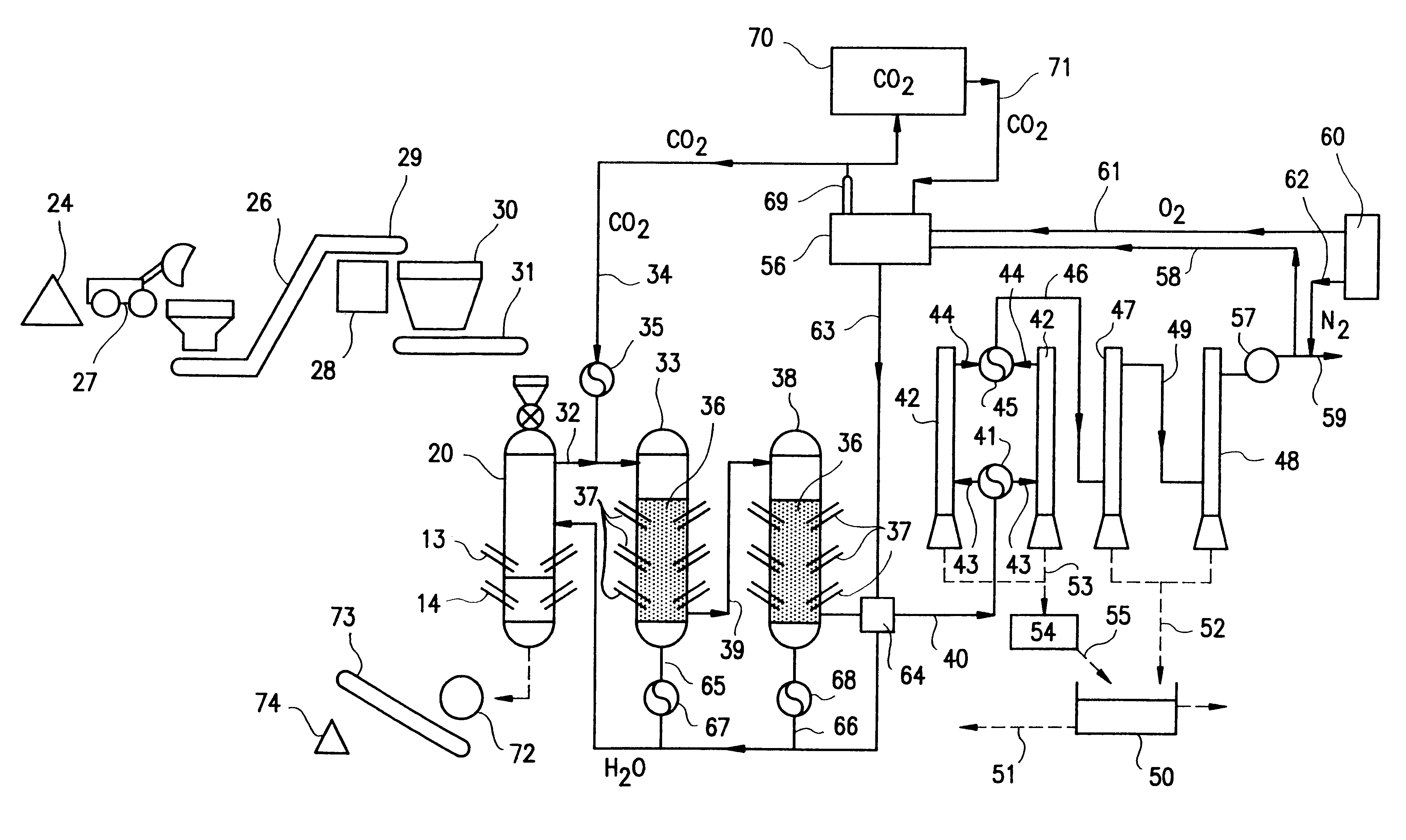
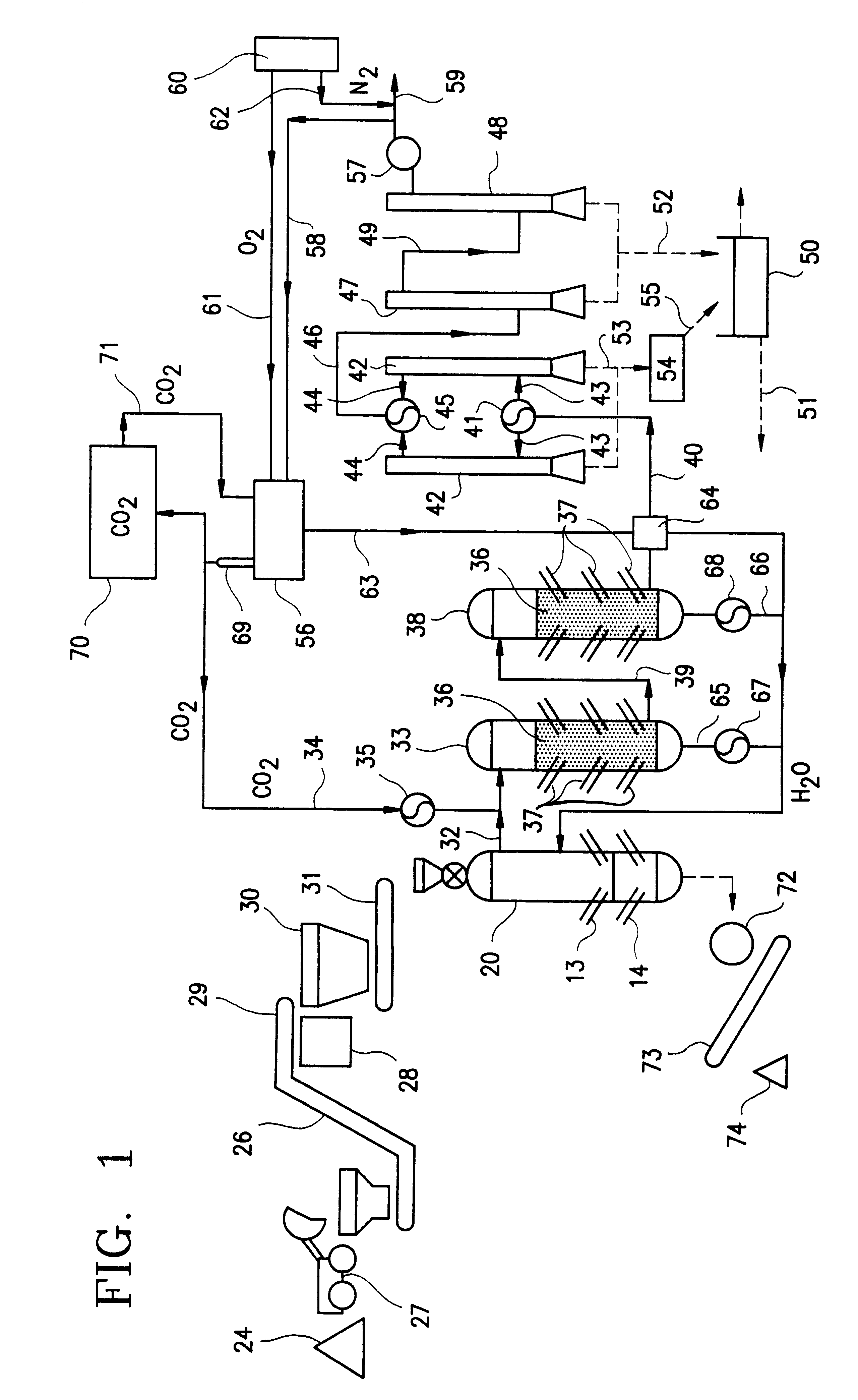
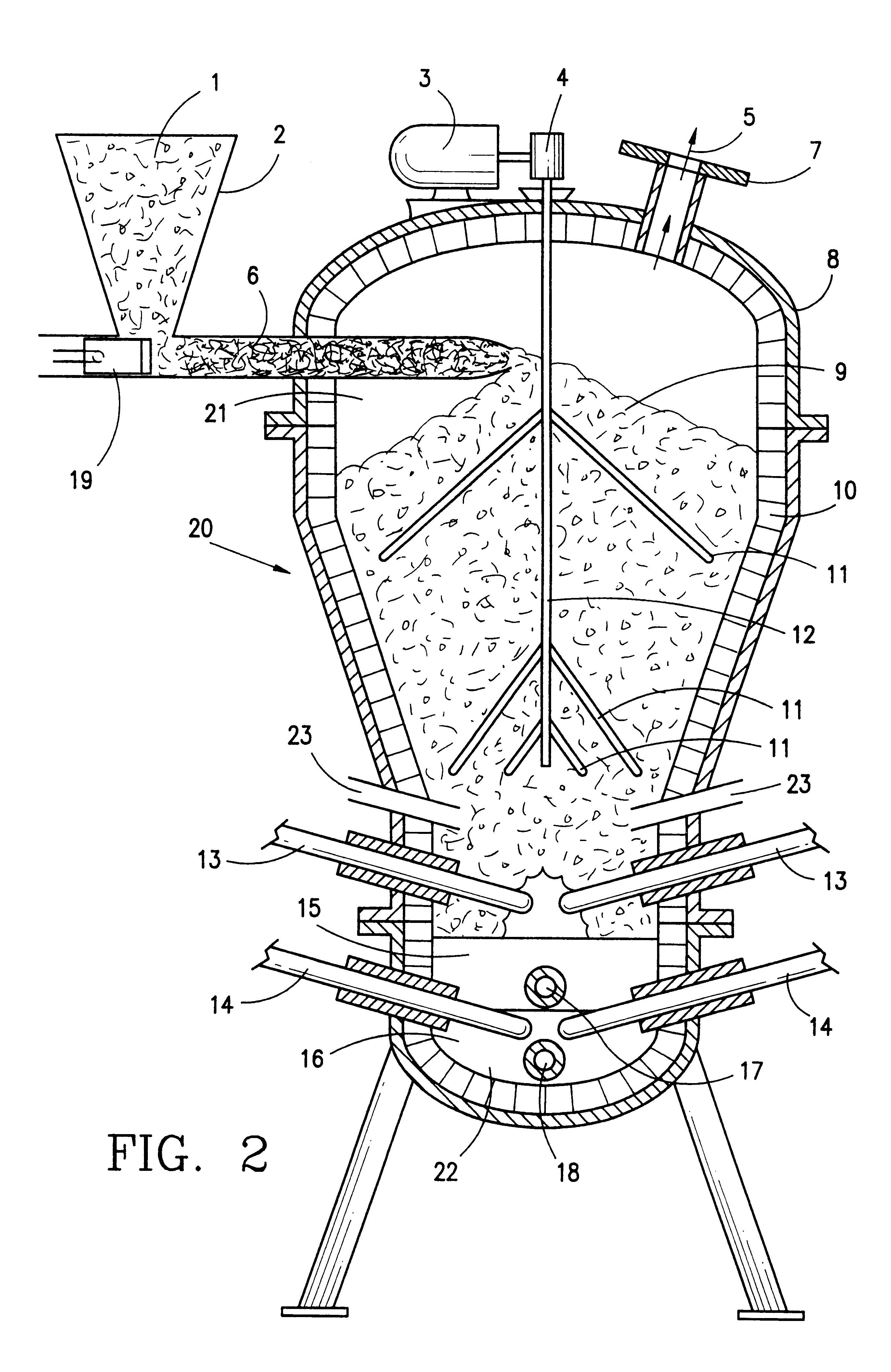
In a preferred embodiment illustrated in FIG. 1, carbonaceous material which is to be pyrolytically decomposed is fed into a primary reactor 20. The preferred primary reactor is illustrated in FIG. 2. The reactor shown in FIG. 2 is a modified version of the primary reactor of U.S. Pat. No. 5,069,765. The modifications include replacing the water reservoir in the bottom portion of the reactor with a vitrification zone equipped with electrodes in the lower portion thereof. These electrodes provide heat for melting the ash for vitrification and melting the metal which enters the bottom portion of the reactor. A steam injection system replaces the water containing reservoir so that the reactor includes a source of water which is required for synthesis gas production in the primary reactor.

The preferred primary reactor indicated generally by reference numeral 20 in FIG. 2 includes chamber 21 which is formed by reactor shell 8. Pyrolytic decomposition occurs in chamber 21.

A vitrification ...


PUM

PropertyMeasurementUnit
mechanical energyaaaaaaaaaa
heataaaaaaaaaa
combustibleaaaaaaaaaa

Abstract

A process and apparatus for producing and burning synthesis gas. Carbonaceous waste material is pyrolytically decomposed in a primary reactor in the presence of steam to produce raw product gas containing H2 and CO. The raw product gas and CO2 is then introduced into a coke containing secondary reactor under pyrolyzing conditions, so that the CO2 and coke react to produce combustible gas having an increased CO content. The combustible gas is mixed with oxygen and CO2 to produce a combustible mixture which is burned as a fuel to produce heat, CO2 and H2O. A portion of the produced CO2 is recovered and used as the source of CO2 gas in the combustible mixture and as a source of CO2 gas for the secondary reactor. Preferably filters and scrubbers are used in a closed loop system to avoid undesirable emissions into the environment.

Description

1. Field of the InventionThe present invention relates to the field of synthesis gas production and to the field of synthesis gas combustion for the generation of power (e.g., generation of electricity) with little or no environmental pollution. In particular, the invention pertains to a closed loop system for the generation and use of synthesis gas for electric power production with zero emissions.2. Background InformationIt is well known in the art that a combustible gas mixture can be produced by the pyrolytic decomposition of a carbonaceous material such as wood, organic refuse, coal and coke. Typically the carbonaceous material is pyrolytically decomposed by contacting hot carbonaceous material with steam under pyrolizing conditions in a vessel. The products of pyrolytic decomposition are mainly hydrogen and carbon monoxide.It is known to produce a combustible gaseous product which comprises hydrogen and carbon monoxide by the water gas system wherein water or steam is reacted ...

Claims


Application Information

Patent Timeline
Patent Type & Authority Patents(United States)
IPC IPC(8): C10B19/00C10J3/68C10J3/00C10B53/00C10J1/207
CPCC10J1/207C10J2200/12C10J2200/154C10J2300/0969C10J2300/0973C10J2300/1634C10J2300/1678
Inventor LEWIS, ARLIN C.
Owner LEWIS GLORIA B
Why Eureka
Try Eureka