Apparatus for cornea reshaping

a technology of a cornea and an apparatus, applied in the field of coupling apparatus, can solve the problems of eyeglasses and contact lenses being inconvenient to wear, eyeglasses and contact lenses being difficult to wear or impediments in daily activities, and reducing the ability of the eye to refract light, so as to prevent accidental exposure of the central optic zone

Inactive Publication Date: 2002-01-29
LASER BIOTECH +1
View PDF43 Cites 127 Cited by
  • Summary
  • Abstract
  • Description
  • Claims
  • Application Information

AI Technical Summary

Benefits of technology

And finally, the coupler acts as a mask to prevent accidental exposure of the central optic zone to any light energy during the irradiance procedure. The masking feature likewise permits selection and control of the geometric pattern for application of light energy. Such control permits specific procedures to be defined and used for specific optical corrections.

Problems solved by technology

In myopia, the refractive power of the eye is excessive meaning that parallel rays of light are focused in front of the retina producing a blurred image.
Eyeglasses and contact lenses may be inconvenient, difficult to wear or impediments in daily activities.
Refractive surgery procedures offer an alternative to eyeglasses and contact lenses but these procedures may be difficult to control in order to achieve accurate refractive corrections.
Radial keratotomy patients may also suffer from side effects and postoperative complications such as fluctuating refraction, glare, reduced night vision, photophobia, endothelial cell loss, and corneal infection.
Another postoperative complication of radial keratotomy is permanent weakening of the cornea due to the fact that the technique requires deep incisions that heal quite slowly.
Trauma to the eyes may result in the rupture of the incisions leading to catastrophic loss of the cornea in some cases.
The laser light causes a breakdown of intramolecular bonds resulting in ablation of tissue by photodecomposition.
As is the case for other forms of refractive surgery, photorefractive keratectomy may lead to inadequate refractive corrections and to undesirable side effects.
Particularly troublesome is the postoperative complication associated with corneal wound repair, a process that tends to "fill in" the ablated cornea volume with a combination of epithelial and stromal tissues.
There are also concerns about the potential phototoxic effect of ultraviolet light generated by corneal tissue fluorescence and the potential toxic effect of molecular ablation products present in the photoablation plume.
The alleged intrastromal photorefractive keratoplasty method is unworkable at some wavelengths and undesirable at other wavelengths because there may be severe damage caused to ocular structures.
However, the direct application of a heated probe is uncontrolled and unavoidably destructive.
This technique caused thermal destruction of the epithelium as well as Bowman's membrane, the important tissue layer immediately underlying the epithelium.
Some patients treated with this technique also showed damage to the deeper corneal stroma and endothelium.
Additionally, this technique often involved inadequate refractive correction.
Severe damage to the corneal tissue still occurs and makes these procedures too undesirable for most ophthalmologists to recommend to their patients.
However, microwave thermokeratoplasty procedures do not provide the spatial and temporal resolution and control required to perform accurate cornea reshaping without excessive thermal damage to cornea structures.

Method used


Image

  • Apparatus for cornea reshaping
  • Apparatus for cornea reshaping
  • Apparatus for cornea reshaping

Examples


Embodiment Construction

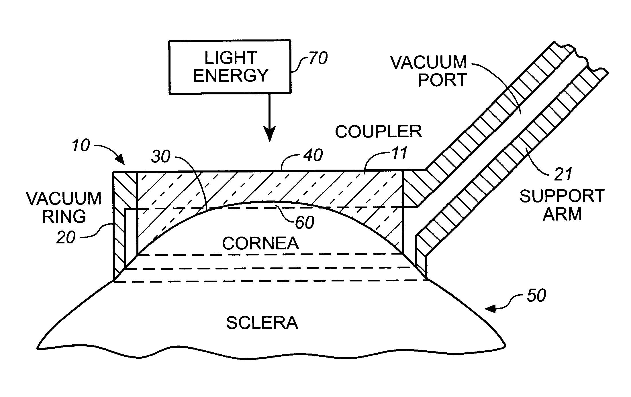
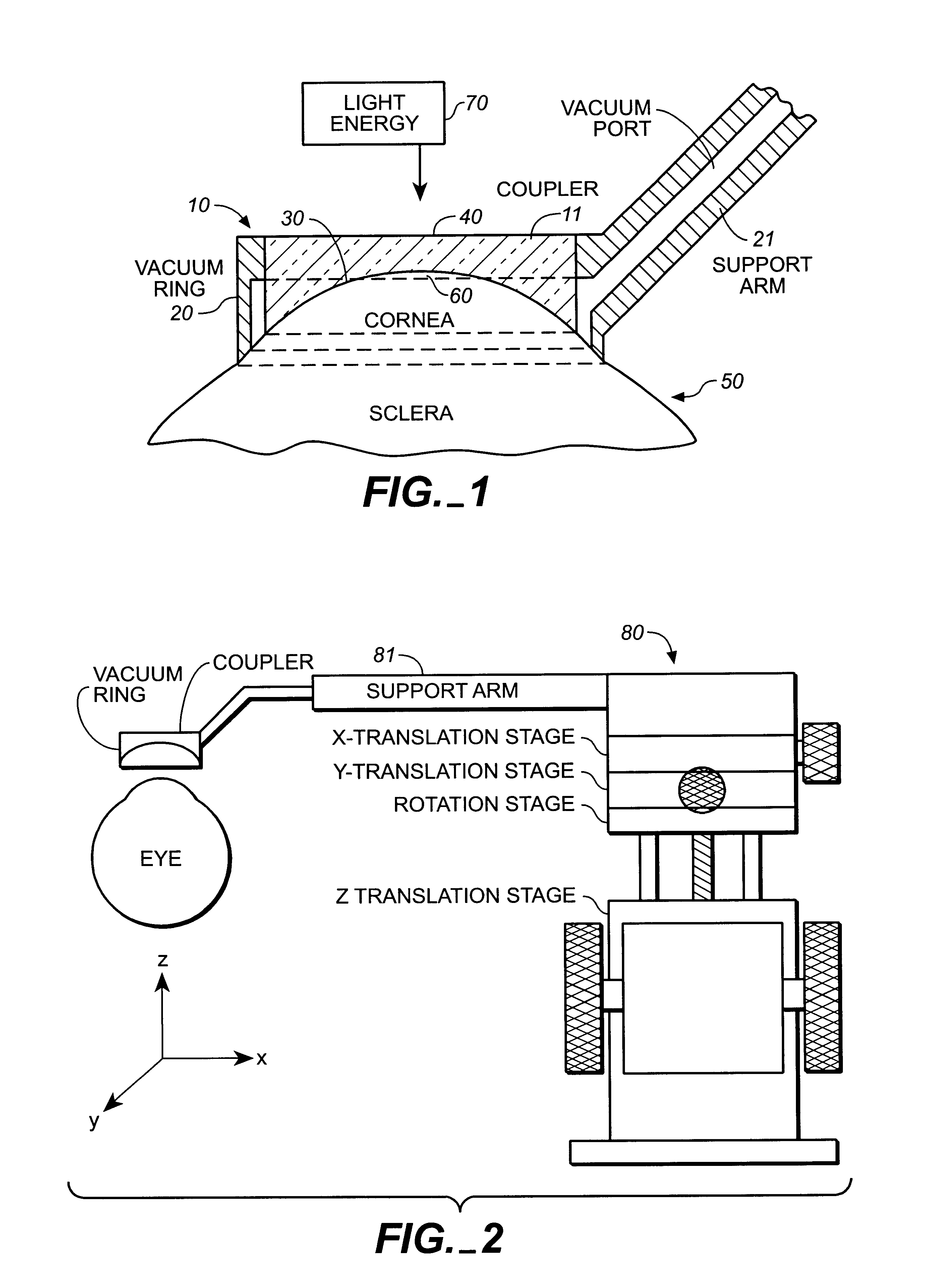
Referring now specifically to FIG. 1, the coupler device is shown in schematic cross section. The primary components of the coupling device 10 are transparent body 11, suction ring 20, corneal engaging surface 30 and masking means 40. The cornea itself is identified by the number 50 and the central optic portion of the cornea by the number 60.

It is an important aspect of this invention that the central optic portion 60 of the cornea 50 is not impacted by the light energy 70 which is emitted from an appropriate energy source, i.e. a hydrogen fluoride or thulium doped laser. By avoiding damage to the central optic zone the possibility of long-term, irreversible damage to vision is avoided. The avoidance or minimizing of risk in the treatment process used in conjunction with the coupler of this invention is an important technical and commercial feature.

The corneal engaging surface 30 of the coupler 10 acts to interface between the coupler device 10 and the cornea 50. The coupler device...


PUM


Abstract

An apparatus is described for use in combination with a noninvasive ophthalmological method for cornea reshaping in order to correct ocular refractive errors such as myopia (nearsightedness), hyperopia (farsightedness), and astigmatism. This apparatus is called a coupler and it is made of a material which is substantially transparent to the light energy used to reshape the cornea. The coupler conducts heat from the anterior portion of the cornea during the heating of the stroma by the light energy. The reshaping is enhanced by the coupler as it has a corneal engaging surface with a radius of curvature which approximates the desired emmetropic shape of the cornea. In addition to being a heat sink and template for the eye, the coupler also acts as a positioner and restrainer of the eye by attaching itself to the eye via an annular suction ring. Finally, the coupler also acts as a mask to prevent accidental exposure of the central optic zone to any light energy during the cornea reshaping procedure.

Description

BACKGROUND OF THE INVENTIONThis invention relates to a coupler apparatus for use in combination with a noninvasive ophthalmological method for reshaping the anterior surface of the cornea in order to achieve emmetropia (i.e., normal vision characterized by the absence of ocular refractive error; the emmetropic eye focuses parallel rays of light onto the retina to produce a clear image). The method of the invention uses light energy to induce thermal changes to the collagen in the stromal portion of the cornea in order to physically reorganize the stromal collagen to produce the desired reshaping of the cornea. The method is described in commonly-assigned, copending U.S. patent application Ser. No. 556,886 filed Jul. 23, 1990 which is hereby incorporated by reference as if fully set forth herein.The apparatus of this invention is referred to as a coupler based on its utility, which is to couple a heat and light energy source to the cornea surface. It is made of a material which is su...

Claims


Application Information

Patent Timeline
Patent Type & Authority Patents(United States)
IPC IPC(8): A61F9/007A61F9/01
CPCA61F9/0079A61F9/008A61F2009/00872A61F2009/00853
Inventor BERRY, MICHAEL J.
Owner LASER BIOTECH
Why Eureka
Try Eureka