Highly compact laser scanning microscope with integrated short-pulse laser

a laser scanning microscope and laser scanning technology, applied in the direction of electrical testing, instruments, electrical circuit testing, etc., can solve the problems of large system, large system, and high cost of short-pulse lasers, and achieve the effect of high-compact microscop

Inactive Publication Date: 2002-03-12
CARL ZEISS MICROSCOPY GMBH
View PDF8 Cites 57 Cited by
  • Summary
  • Abstract
  • Description
  • Claims
  • Application Information

AI Technical Summary

Benefits of technology

integration of a short-pulse laser in the scan module of a laser scanning microscope for providing a highly compact microscope system;

Problems solved by technology

The short-pulse lasers that are used (wavelength-tunable lasers as well as fixed wavelength lasers) are, among other things, very bulky and, because of their great technical complexity, very expensive and can only be handled with difficulty by the user.
This generally requires long optical beam paths which renders the system sensitive to adjustment and results in very large systems because of the extent of the optical beam path.
The frequently required adjustment of the laser (particularly also when the laser wavelength is changed or tuned) results, among other things, in spatial drifting of the laser beam coupled out of the laser.
Consequently, the laser beam is no longer optimally adjusted within the laser scanning microscope.
This kind of fiber coupling of a short-pulse laser in a laser scanning microscope is basically possible, but is very problematic for the short pulses due to the optical scattering of the glass fibers and nonlinear optical effects such as self-phase modulation, Brillouin scattering, Raman scattering, etc. which can occur at the high laser intensities in the glass fiber core.

Method used


Image

  • Highly compact laser scanning microscope with integrated short-pulse laser
  • Highly compact laser scanning microscope with integrated short-pulse laser
  • Highly compact laser scanning microscope with integrated short-pulse laser

Examples


Embodiment Construction

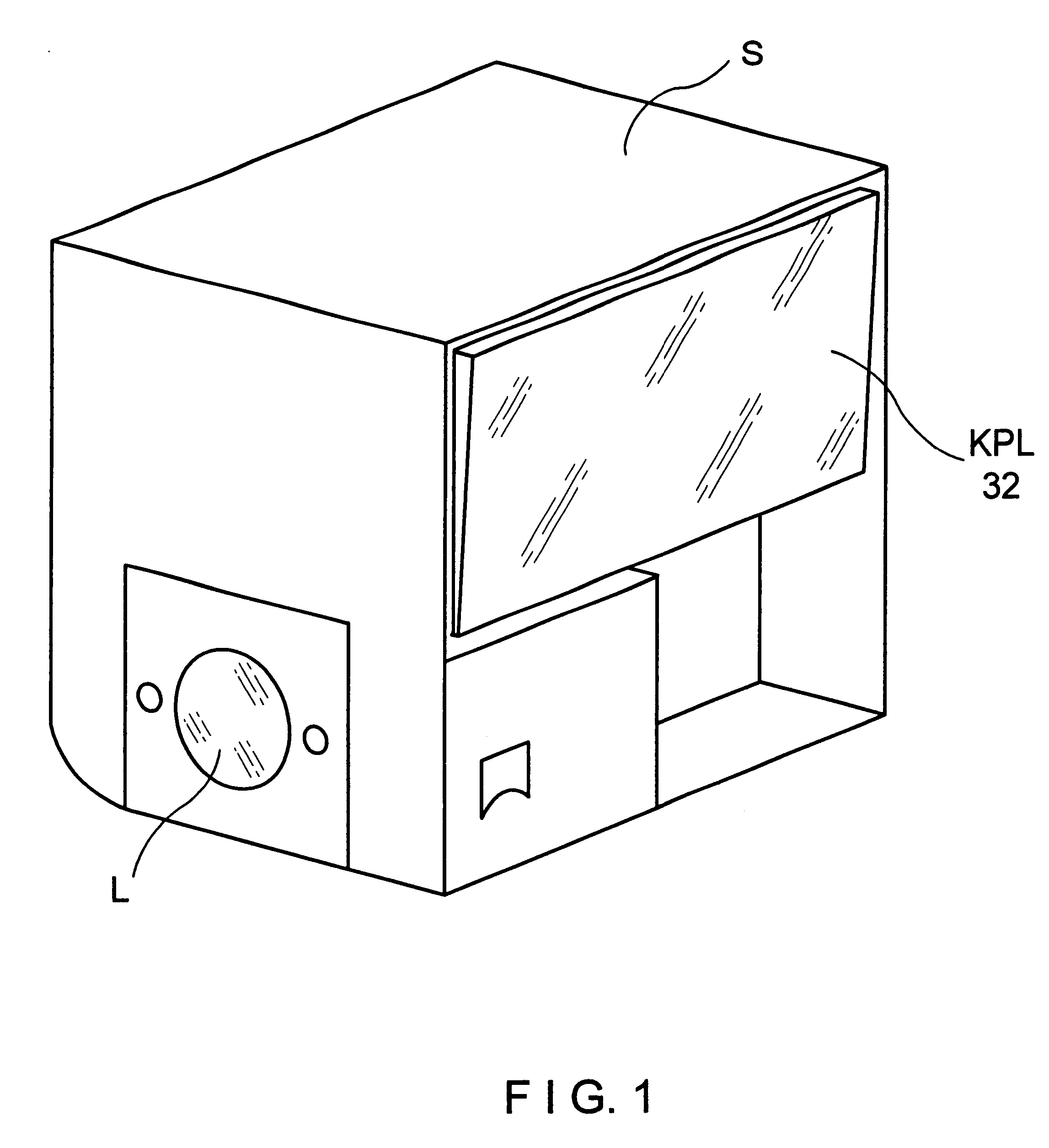
FIG. 1 shows schematically the housing of a scan head S which is connectable with a microscope beam path via a light passage opening L, wherein the scan head S is described in detail with reference to the subsequent Figures.

Integrated within this housing is the housing of a short-pulse laser KPL 32 which accordingly forms a compact unit with the scan head S.

A cover, not shown, is advantageously provided at the housing of the scan head and accordingly also covers the laser 32.

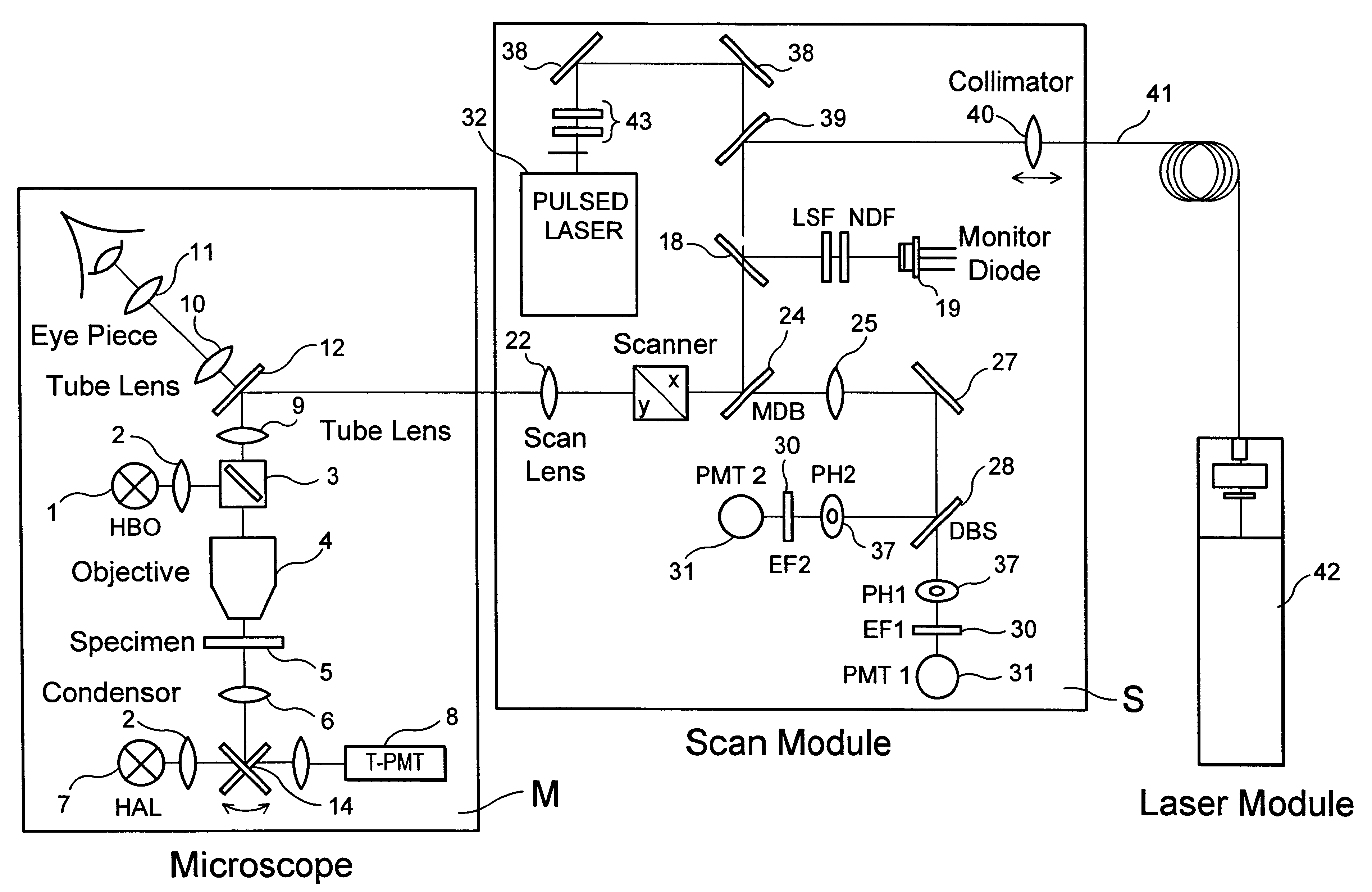
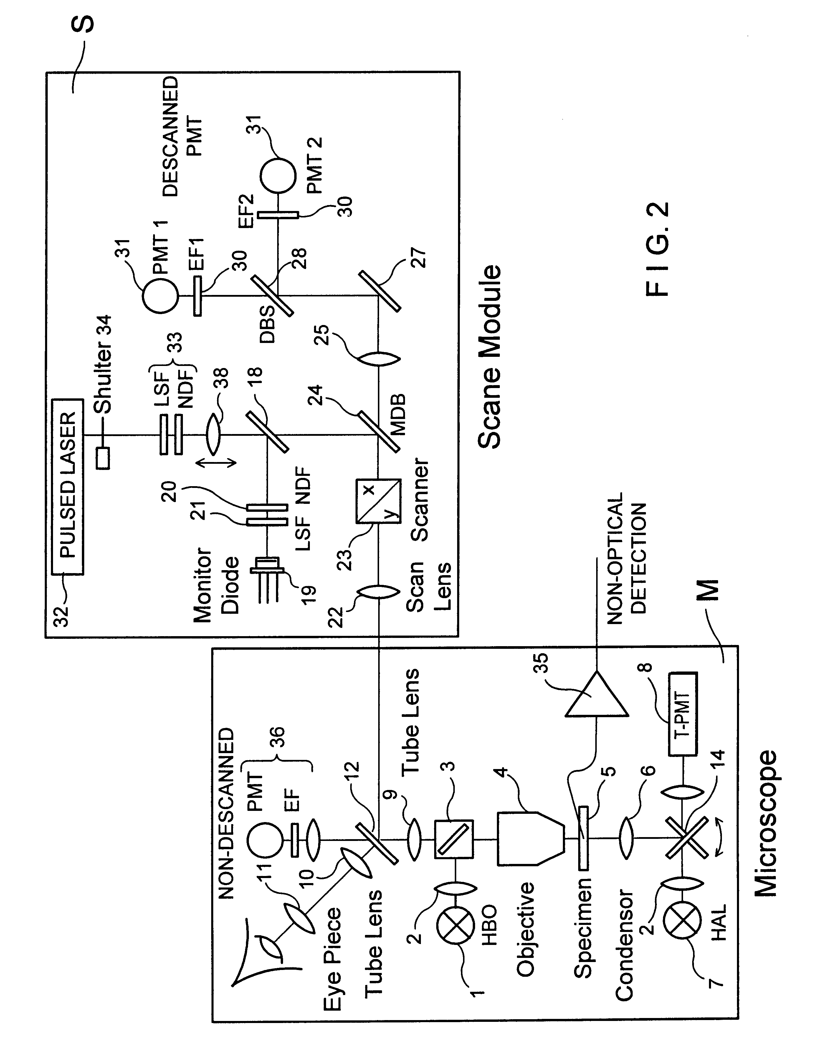
FIG. 2 is a schematic view of a microscope unit M and a scan head S sharing a common optical interface.

The scan head S can be attached to the photo tube of an upright microscope and also advantageously to a side output of an inverse microscope (DE 4323129 A1).

FIG. 2 shows a microscope beam path which can be switched between reflected-light scanning and transmitted-light scanning by means of a swivelable mirror and which has a light source 1, illumination optics 2, beam splitter 3, objective 4, specimen 5, conden...


PUM


Abstract

The invention describes a highly compact laser scanning microscope with integrated short-pulse laser. Direct coupling or a fiber coupling of the short-pulse laser with the laser scanning microscope is advantageously circumvented with this arrangement. This compact arrangement of the laser in the scan module of the laser scanning microscope can be used in a particularly advantageous manner, for example, in multiphoton microscopy for three-dimensionally resolved microscopic analysis, e.g., of biological specimens. Because of the inherent depth discrimination of the multiphoton technique, confocal pinholes can be entirely omitted in the detection beam path. Accordingly, the microscope system can be realized in a very simple manner with respect to engineering and is particularly simple to handle with respect to application. Through the use of a short-pulse laser system in which a plurality of wavelengths are available simultaneously, diverse applications can be realized in one and the same compact microscope system.

Description

The present invention relates to a highly compact laser scanning microscope with integrated short-pulse laser.Laser scanning microscopes using short-pulse lasers (e.g., picosecond or femtosecond lasers) have long been known, primarily in time-solved and multiphoton microscopy.WO 91 / 07651 discloses a two-photon laser scanning microscope with excitation through laser pulses in the subpicosecond range at excitation wavelengths in the red or infrared region.EP 666473A1 WO 95 / 30166, DE 4414940 A1 describe excitations in the picosecond range, and beyond, with pulsed or continuous radiation.A process for optical excitation of a specimen by means of two-photon excitation is described in DE C2 4331570.DE 29609850 by the present Applicant describes coupling of the radiation of short-pulse lasers into a microscope beam path via light-conducting fibers.The short-pulse lasers that are used (wavelength-tunable lasers as well as fixed wavelength lasers) are, among other things, very bulky and, bec...

Claims


Application Information

Patent Timeline
Patent Type & Authority Patents(United States)
IPC IPC(8): G02B21/00G01Q30/02
CPCG02B21/002
Inventor SIMON, ULRICHWOLLESCHENSKY, RALF
Owner CARL ZEISS MICROSCOPY GMBH
Why Eureka
Try Eureka