
Magnetic nerve stimulation seat device

a seat device and magnetic nerve technology, applied in the field of magnetic nerve stimulation seat devices, can solve the problems of aggravated problems, affecting the efficiency of nerve or muscle tissue excitation, so as to improve the efficiency and rate, reduce the effect of excitation

Inactive Publication Date: 2002-12-31
MAGIC RACE
View PDF7 Cites 151 Cited by
  • Summary
  • Abstract
  • Description
  • Claims
  • Application Information

AI Technical Summary

Benefits of technology

To accomplish the objectives of the present invention, a magnetic nerve stimulator is provided herein which can be used to stimulate nerves without the need for surgery. Magnetic stimulation of peripheral nerves has the advantages of convenience and threshold variability over competing FES systems. An advance of the present invention over competing magnetic nerve stimulators is in the use of a highly saturable magnetic core, i.e. a permeable core of high field saturation, and in the design of the magnetic core stimulator itself.
Such an excitation would have the effect of kneading the muscle tissue group along its longitudinal axis. This particular excitation pattern may be instrumental in more fully recruiting larger muscle groups such as the hamstring group in the leg. Full recruitment or stimulation of the nerve group would be advantageous to long term rehabilitation. Preliminary experiments with the device indicate that excitations at the frequencies mentioned accomplish exercise of the muscles at a higher efficiency and rate than could be accomplished through normal means.
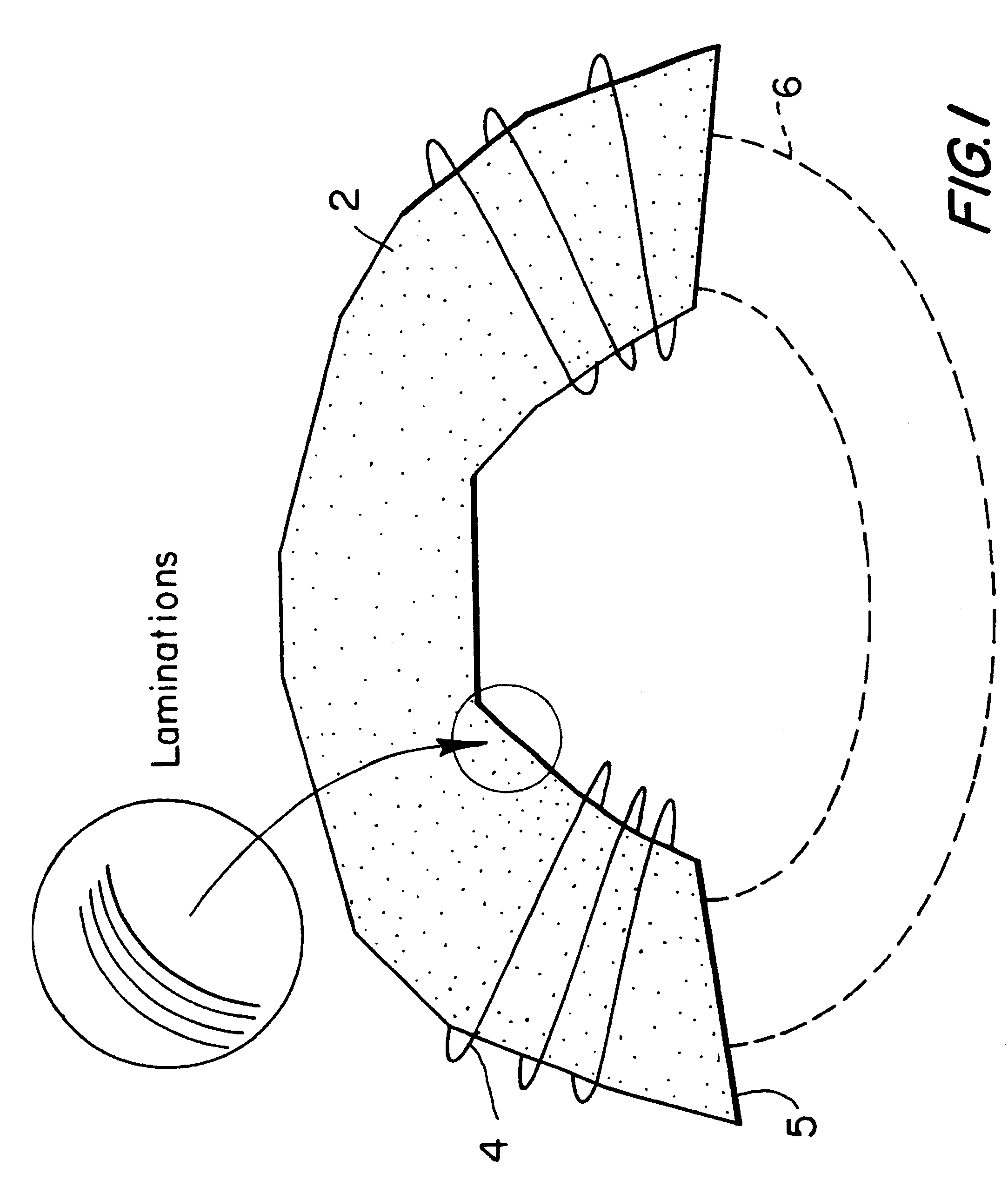
In summary, it is noted that there are a number of ways to more efficiently stimulate various muscle groups within the body. The key to these more efficient techniques revolves around using a thin laminate material of high magnetic field saturation to construct these cores and thereby drive and focus the flux into the regions desired. A simple "C" type core achieves a reluctance advantage of at least a factor of two over conventional cores. By using multiple cores connected at a center leg, a single focus site can be achieved with the return path disbursed in two or more areas so as to discourage excitation when the field is returned. In other applications, multiphased coils that actually enclose the tissue of interest can be excited so as to roll or knead muscle groups directionally with time. Certain wrapping applications may be more instrumental for higher recruitment of injured muscle groups.
FIG. 6 is an end view of the leg or arm stimulator. The winding going from one section to the next is taken out in a long fold to allow for ease of opening of the core units for facilitating placement around the leg or arm.

Problems solved by technology

Unless this half-cell reaction is maintained in the reversible regime, necrosis will result--partially because of the oxidation of the half-cell reaction and partially because of the chemical imbalance accompanied by it.
The disadvantage however, is that it involves half-cell reactions.
Long term excitation of nerve or muscle tissue is often accompanied by skin irritation due to the current concentration at the electrode / skin interface.
This problem is especially aggravated when larger excitation levels are required for more complete stimulation or recruitment of the nerve group.
That is, the electrical current that ideally would be injected through the skin to excite the muscle groups of interest often leads to some skin irritation with time.
Second, and more importantly, the previous nerve stimulation work is dominated almost exclusively by air core coils of various shapes and sizes.
Toroidal cores are not preferred, as it is has been found that an open core can be more effectively utilized to focus the magnetic field produced by the stimulator, and as the suitability of toroidal cores have been found to be limited to invasive applications.
The cut will destroy the electrical isolation of adjacent laminations.
Failure to perform this deep etch results in considerable eddy current loss and heating at the cut ends of the core.
One group which can be particularly difficult to stimulate is the abdominal wall.

Method used


Image

  • Magnetic nerve stimulation seat device
  • Magnetic nerve stimulation seat device
  • Magnetic nerve stimulation seat device

Examples


Embodiment Construction

In accordance with the present invention, a magnetic nerve stimulator is provided which can be used for non-invasive stimulation of nerves in the peripheral nervous system. The advantage of non-invasive stimulation is a significant one, as nerves can be stimulated deep beneath the surface of the skin without the necessity for surgery, incisions in the body, or the use of uncomfortable electrodes. To achieve an effective non-invasive stimulator, however, the stimulator must be carefully designed to achieve sufficient depth and penetration within the body so as to effectively stimulate the nerves or nerve groups of interest.

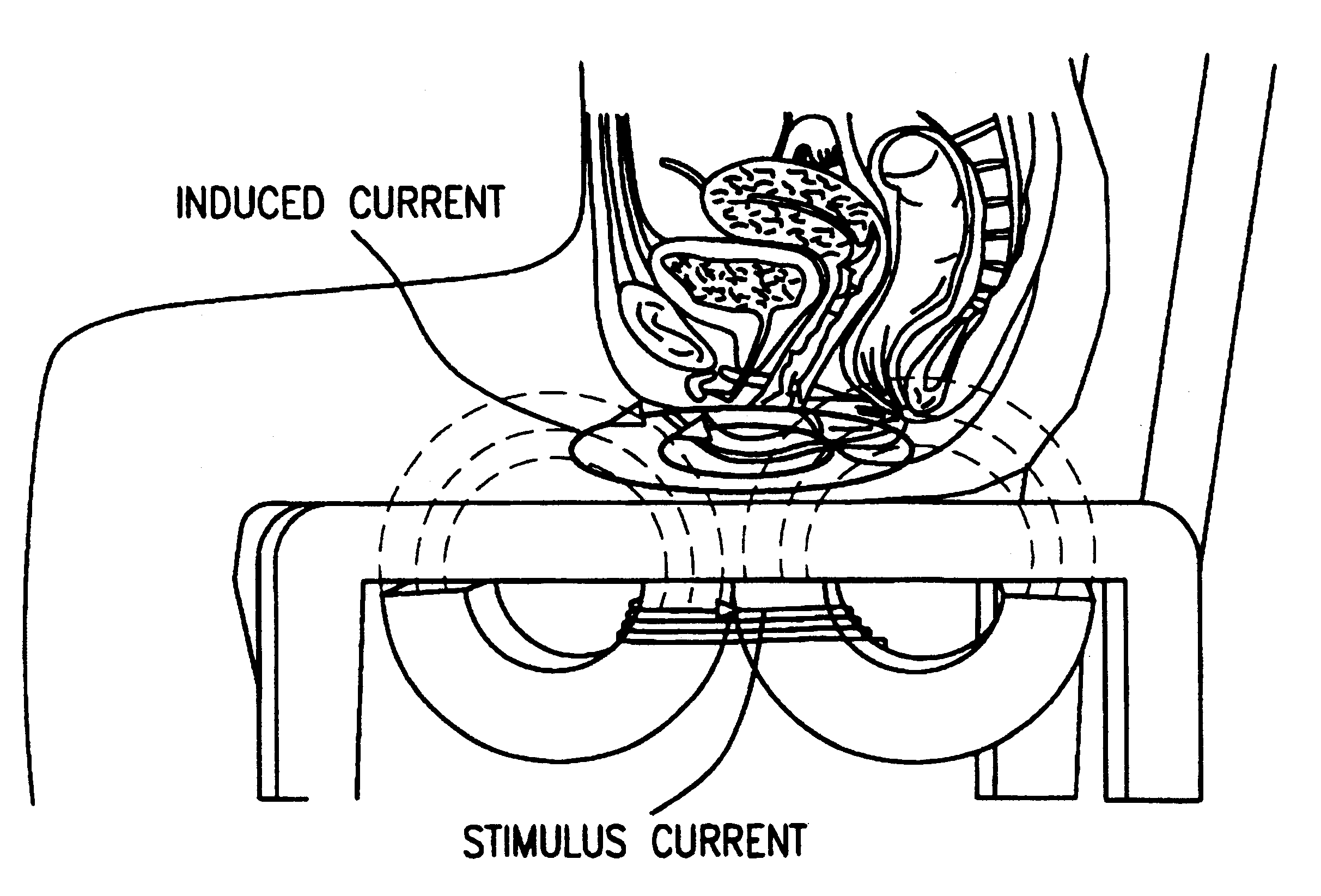
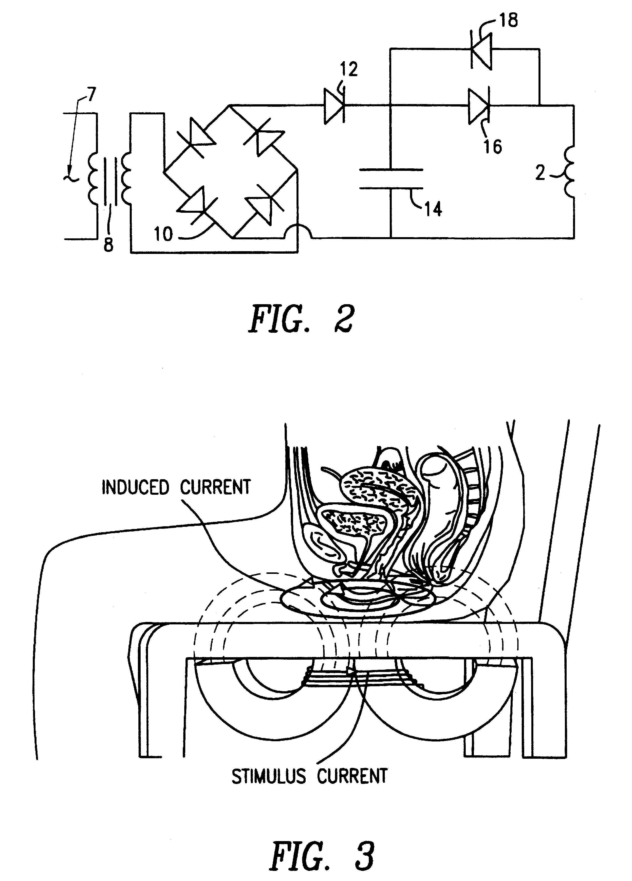
The present inventors have recognized the objective of highly effective non-invasive stimulation by providing a magnetic nerve stimulator which can achieve significant depth and penetration, such that internal human nerve groups can be stimulated to treat incontinence, achieve muscle rehabilitation (or conditioning) or assist with weight loss.

In the preferred embod...


PUM


Abstract

A magnetic nerve stimulator system is comprised of a core constructed from a material having a high field saturation with a coil winding. A thyrister capacitive discharge circuit pulses the device. A rapidly changing magnetic field is guided by the core, preferably vanadium permendur. For task specific excitation of various nerve groups, specially constructed cores allow for excitation of nerves at deeper levels with higher efficiency than is possible with air-core stimulators. Among the applications possible with this invention are treatment of incontinence, rehabilitation of large muscle groups in the leg and arm, and excitation of abdominal wall muscle groups to aid in weight loss and metabolic rate increase. A C-shape is employed for focussing the stimulation as desired.

Description

BACKGROUND OF THE INVENTION AND DESCRIPTION OF THE PRIOR ARTA nerve cell can be excited in a number of different ways, but one direct method is to increase the electrical charge within the nerve, thus increasing the membrane potential inside the nerve with respect to the surrounding extracellular fluid. One class of devices that falls under the umbrella of Functional Electrical Stimulation (FES) realizes the excitation of the nerves by directly injecting charges into the nerves via electrodes which are either placed on the skin or in vivo next to the nerve group of interest. The electric fields necessary for the charge transfer are simply impressed via the wires of the electrodes.FES is accomplished through a mechanism which involves a half-cell reaction. Electrons flow in wires and ions flow in the body. At the electro-electrolytic interface, a half-cell reaction occurs to accomplish the electron-ion interchange. Unless this half-cell reaction is maintained in the reversible regime...

Claims


Application Information

Patent Timeline
IPC IPC(8): A61N2/00A61N2/02A61N2/04
CPCA61N2/02Y10S128/25
Inventor DAVEY, KENT R.EPSTEIN, CHARLES M.
Owner MAGIC RACE
Learn More