Sectored magnetic lens and method of use

a magnetic lens and sectored technology, applied in the field of magnetic lenses, can solve the problems of affecting the working affecting the efficiency of the integrated circuit, and affecting the use of the optical microscope,

Inactive Publication Date: 2003-02-04
KLA TENCOR TECH CORP
View PDF28 Cites 37 Cited by
  • Summary
  • Abstract
  • Description
  • Claims
  • Application Information

AI Technical Summary

Problems solved by technology

Optical microscopes generally have an inherent resolution limit of approximately 200 nm and have limited usefulness in current manufacturing processes.
High voltage electrons may penetrate deep into a semiconductor substrate or a portion of a semiconductor formed upon a semiconductor substrate thereby damaging the substrate or the device and rendering it unsuitable as a working device such as an integrated circuit.
Therefore, low voltage electron beams may typically used to analyze delicate semiconductor specimens that otherwise might be damaged by high voltage electron sources.
The primary factor that reduces resolution in the low acceleration voltage region is blur of the electron beam due to chromatic aberration.
Dispersion in the energy of the electron beam emitted from the electron source typically causes chromatic aberration.
Although electron beams may be deflected by this lens, astigmation may still be a problem.
The overall alignment of the lens system, however, may be non-colinear due to the incorporation of such a separate feature.
Therefore, complexity of the overall alignment of the system increases when the charged particle beam is forced to pass through successive non-colinear points.
There are, however, several disadvantages to the lens systems described above.
For example, axially symmetric lenses may typically suffer from hysteresis, large inductance of the excitation coil, and thermal stability problems.
Hysteresis may cause a relationship between the excitation coil current and the deflected beam position to depend upon past deflection history.
Therefore, accurate focus of an electron beam using the magnetic lens may be extremely difficult to maintain and control.
Additionally, large inductance of the excitation coil may cause thermal stability problems due to heat generated by the lens or the excitation coils.
Therefore, the center of the lens may shift due to thermal expansion of the materials used to construct the lens.
Immersion lenses are also limited in their application to a variety of specimens.
Due to space limitations, immersion lenses may not be able to accommodate a large specimen such as a semiconductor substrate.
Modifying these lenses in order to accommodate such large semiconductor substrates may also adversely affect the performance of immersion lenses.
Alternatively, reducing the size of the semiconductor substrate by cross-sectioning the wafer is not usually an option due to the cost associated with destroying a product wafer.
Asymmetric immersion lenses may be more flexible to accommodate large specimen such as semiconductor substrates, but these lenses may have a reduced capability to detect secondary electrons.
For example, because secondary electrons may be emitted at a point beyond the magnetic field peak, low energy secondary electrons may not be able to surmount the magnetic field maximum.
In addition to the above disadvantages, the performance of magnetic lenses may also be limited due to changes in the magnetic field strength due to low frequency noise, drift in the performance of current drive electronics, drift due to eddy currents or superimposed fields from other sources, and drift in the magnetic field strength over time from other causes.
Although a magnetic lens design may minimize these effects on the performance of the lens, it may not be possible to substantially eliminate magnetic field drift of the lens.
For example, eddy currents due to magnetic flux leakage from a lens through a gap in the magnetic lens may adversely affect the performance of the magnetic lens.
Because a magnetic lens must be designed with a bore to allow the electron beam to travel through the lens, however, it is impossible to seal the magnetic lens off completely.
As a result, some of the magnetic field will inherently "leak" out of a magnetic lens.
Therefore, the effects of eddy currents on the performance of a magnetic lens may not be completely eliminated due to usage requirements.
Drift in the magnetic field may cause the electron beam to drift out of focus.
Mechanical focus methods, however, may be slow due to the time required for moving the devices.
In addition, microscopic vibrations due to mechanical motion of the alignment yoke may need to settle before the magnetic lens may perform adequately.
Hysteresis in the magnetic field strength may also be induced from frequent changes in the voltage supplied to a magnetic lens.
Therefore, frequently adjusting the beam voltage may increase the complexity of a current history of the lens.
As the complexity of the current history increases, hysteresis will also become more problematic.
Therefore, estimating the magnetic field strength using measurements of the current in the lens coil may induce error in this method.
In addition, the coil and the core materials may react in a non-ideal way to the frequent changes in the current being supplied to the coil.
A thorough degaussing procedure may reduce the effects of hysteresis, however, magnetic hysteresis typically remains a problem in most magnetic lenses.
Although such a method for focusing the electron beam may reduce deleterious effects of hysteresis in the current of the magnetic objective lens, other factors that may lead to defocusing may not be addressed in this design.
For example, as mentioned above, other factors that may hinder the performance of a magnetic lens may include thermal changes in the material properties, drift in the current drive electronics, drift in the magnetic field due to eddy currents, and drift due to superimposed fields from other sources.
The resulting magnetic field, however, may follow a nonlinear relationship with the current due to hysteresis in the magnetic lens and the behavior of the coil and the core materials in response to the change in current.
This iterative method also depends on operator judgement and is consequently subject to error.
More importantly, the additional sources of magnetic field drift described above may also cause this magnetic field to be irreproducible.
Such air gaps may induce eddy currents in the outer pole pieces and the lens coil.
As the dimensions of devices shrink, it is becoming increasingly difficult to successfully fabricate semiconductor devices.
Therefore, the initial magnetic potential may not sufficiently reduce aberrations in, or focus, the charged particle beam in order to obtain an adequate image of the specimen.
Magnetic field drift may occur due to the performance of the electron beam source, hysteresis effects within the magnetic lens, temperature dependent properties of the magnetic lens, and / or drift caused by sources external to the magnetic lens.
As such, the low-pass filter element may prevent fluctuations in the current supplied to the magnetic lens, which may adversely affect the performance of the magnetic lens.

Method used


Image

  • Sectored magnetic lens and method of use
  • Sectored magnetic lens and method of use
  • Sectored magnetic lens and method of use

Examples


Embodiment Construction

Effect of Magnetic Field Feedback Control on a Magnetic Lens

FIG. 7 illustrates a plot of the hysteresis of a magnetic lens using a current feedback control apparatus. The magnetic field strength was estimated by measuring the current in the lens coil. The current in the lens coil was varied to alter the magnetic field strength of the magnetic lens. Variations in the current in the lens coil were highest at the beginning of testing and were decreased over time. The first current, which was applied to the lens coil, has been designated as the point on the graph which has been labeled "start." The last current, which was applied to the lens coil, has been designated as the point on the graph which has been labeled "end." The measured magnetic field has been plotted versus the desired magnetic field. The range of the measured magnetic field and the desired magnetic field range from approximately -10 gauss to approximately +10 gauss. As shown in FIG. 7, the measured magnetic field has a ...


PUM

PropertyMeasurementUnit
sizeaaaaaaaaaa
sizeaaaaaaaaaa
magnetic fieldaaaaaaaaaa

Abstract

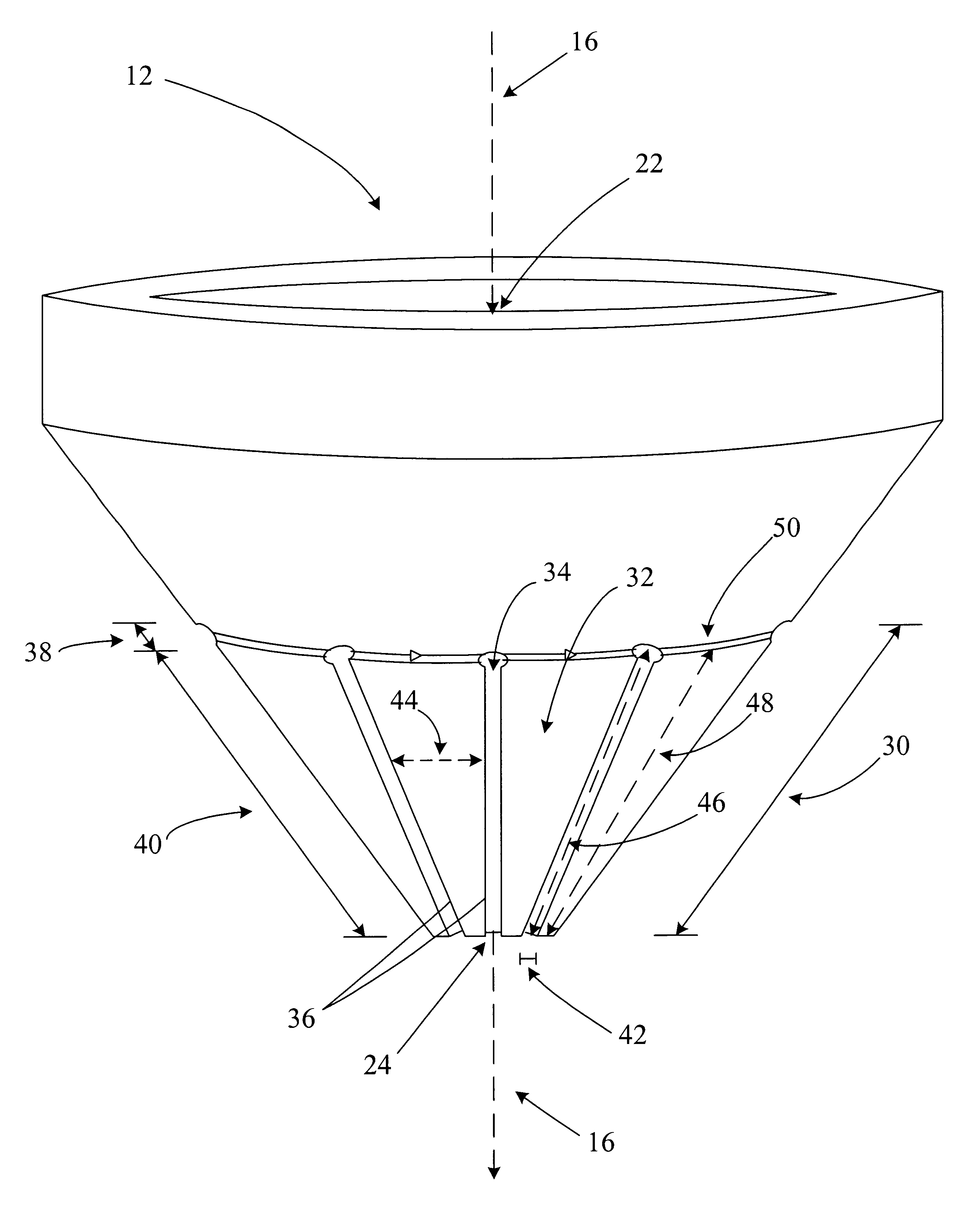
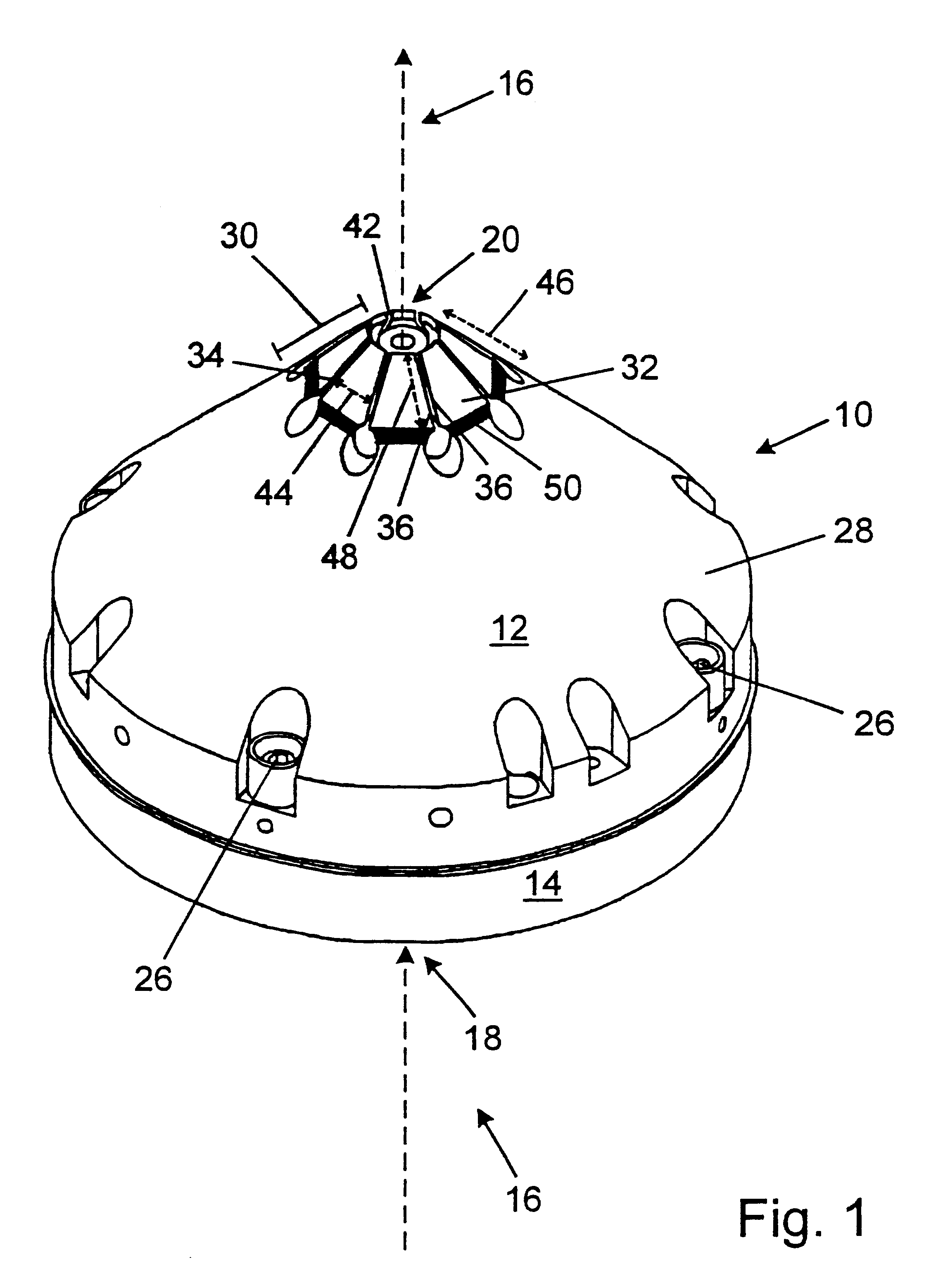
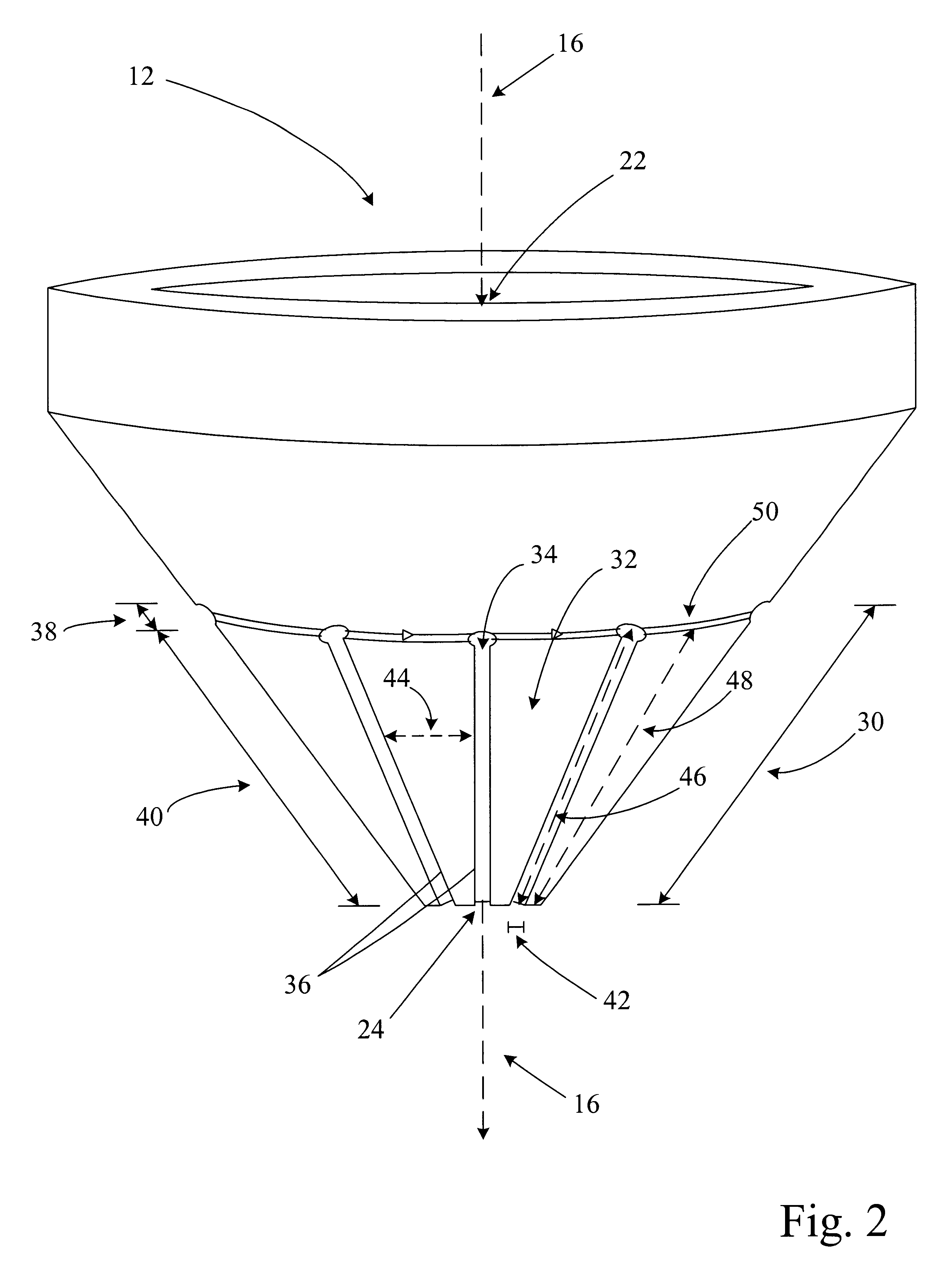
A magnetic lens configured to apply a magnetic field to a charged particle beam is provided. The magnetic lens may include an outer pole piece and an inner pole piece. The outer pole piece may have at least two sectors and at least two slots. The magnetic lens may also have a primary coil winding interposed between the outer pole piece and the inner pole piece. In addition, the magnetic lens may have a number of sector coil windings, and each sector of the outer pole piece may be coupled to one sector coil winding. A magnetic potential of the outer pole piece relative to the inner pole piece may be generated by applying a current to the primary coil winding. A separate magnetic potential of each sector may also be generated by applying a current to the respective sector coil windings of each sector of the outer pole piece.

Description

1. Field of the InventionThis invention generally relates to a magnetic lens that may be configured to apply a magnetic field to a charged particle beam. Certain embodiments relate to a sectored magnetic lens that may be incorporated into a scanning electron microscope system.2. Description of the Related ArtAs the dimensions of semiconductor devices continue to shrink with advances in semiconductor materials and processes, the ability to examine microscopic features and to detect microscopic defects has become increasingly important in the successful fabrication of advanced semiconductor devices. Significant research continues to focus on increasing the resolution limit of metrology tools that are used to examine microscopic features and defects. Optical microscopes generally have an inherent resolution limit of approximately 200 nm and have limited usefulness in current manufacturing processes. Microscopes that utilize electron beams to examine devices, however, may be used to inv...

Claims


Application Information

Patent Timeline
Patent Type & Authority Patents(United States)
IPC IPC(8): G01N23/00H01J37/10H01J37/141H01J37/21H01J37/26H01J37/28
CPCH01J37/141H01J37/21H01J37/28H01J37/265H01J2237/1405
Inventor NOTTE, IV, JOHN A.
Owner KLA TENCOR TECH CORP
Why Eureka
Try Eureka