Solder ball and method for producing same

a technology of solder ball and ball head, which is applied in the field of solder ball, can solve the problems of poor supply of solder ball, insufficient soldering, and low production efficiency

Inactive Publication Date: 2003-02-11
DUKSAN HI METAL
View PDF8 Cites 54 Cited by
  • Summary
  • Abstract
  • Description
  • Claims
  • Application Information

AI Technical Summary

Benefits of technology

Accordingly, an object of the present invention is to provide a solder ball having high sphericity, high dimension accuracy, narrow dimension distribution and smooth and clean surface, and a method for producing such a solder ball.
When the separate melt droplets 9 falling in the chamber 7 are electrically charged when passing between high voltage electrode plates 23 (FIG. 2), the merger of the melt droplets 9 can effectively be prevented by electric repulsion force given to the melt droplets 9.

Problems solved by technology

If the solder balls had poor sphericity, resulting in poor rolling, then they might stop in the apparatus, resulting in poor supply of the solder balls.
This necessitates frequent adjustment of the apparatus, leading to lower production efficiency.
If there were large distribution in the diameters of the solder balls, there would arise a large gap between the solder balls having small diameters and lands of the substrate at the time of reflow soldering, resulting in insufficient soldering and thus poor connection.
Because mechanically cut of cold-worked materials are usually used as solder materials in the in-oil spheroidizing method, it is difficult to make the size of the solder material uniform due to wear of cutting tools.
Therefore, the in-oil spheroidizing method is disadvantageous in failing to providing uniform solder balls.
In this case, solder balls having ragged surfaces are not attracted by the nozzles, resulting in the production of poor BGA packages in which all solder balls are not necessarily arranged at predetermined positions.
In the case of the in-oil spheroidizing method, however, smooth surface cannot be maintained if the oil deteriorates, necessitating frequent change of the oil and thus poorer production efficiency.
If impurities remain on the surfaces of the solder balls, or if carbon-concentrated layers or oxygen-concentrated layers exist on the solder ball surfaces, carbons and oxides remain on the connected surfaces as scum when melting the solder balls for connection, resulting in poor wettability of the solder and thus poorer connection reliability.
In the oil-spheroidizing method, the resultant solder balls are contaminated with oil, necessitating a degreasing treatment.
In the case of the alkaline degreasing, alkaline ion in the alkaline aqueous solution is introduced into the semiconductor materials, making it likely to cause erroneous operations of the semiconductor devices.
Also the degreasing with an organic solvent is disadvantageous in that there is no organic solvent, which is safe and does not destroy the ozone layer.
Further, with respect to the characteristics of solder balls, degreasing with trichloroethane is disadvantageous in that it provides the solder balls with poor wettability.
Also, if the surface of solder balls was contaminated, oxidized layers cannot be removed even with a flux.
Further, adjacent balls are coagulated by the oil at the time of mounting the solder balls, failing to achieve good mounting.

Method used


Image

  • Solder ball and method for producing same
  • Solder ball and method for producing same
  • Solder ball and method for producing same

Examples


example 3

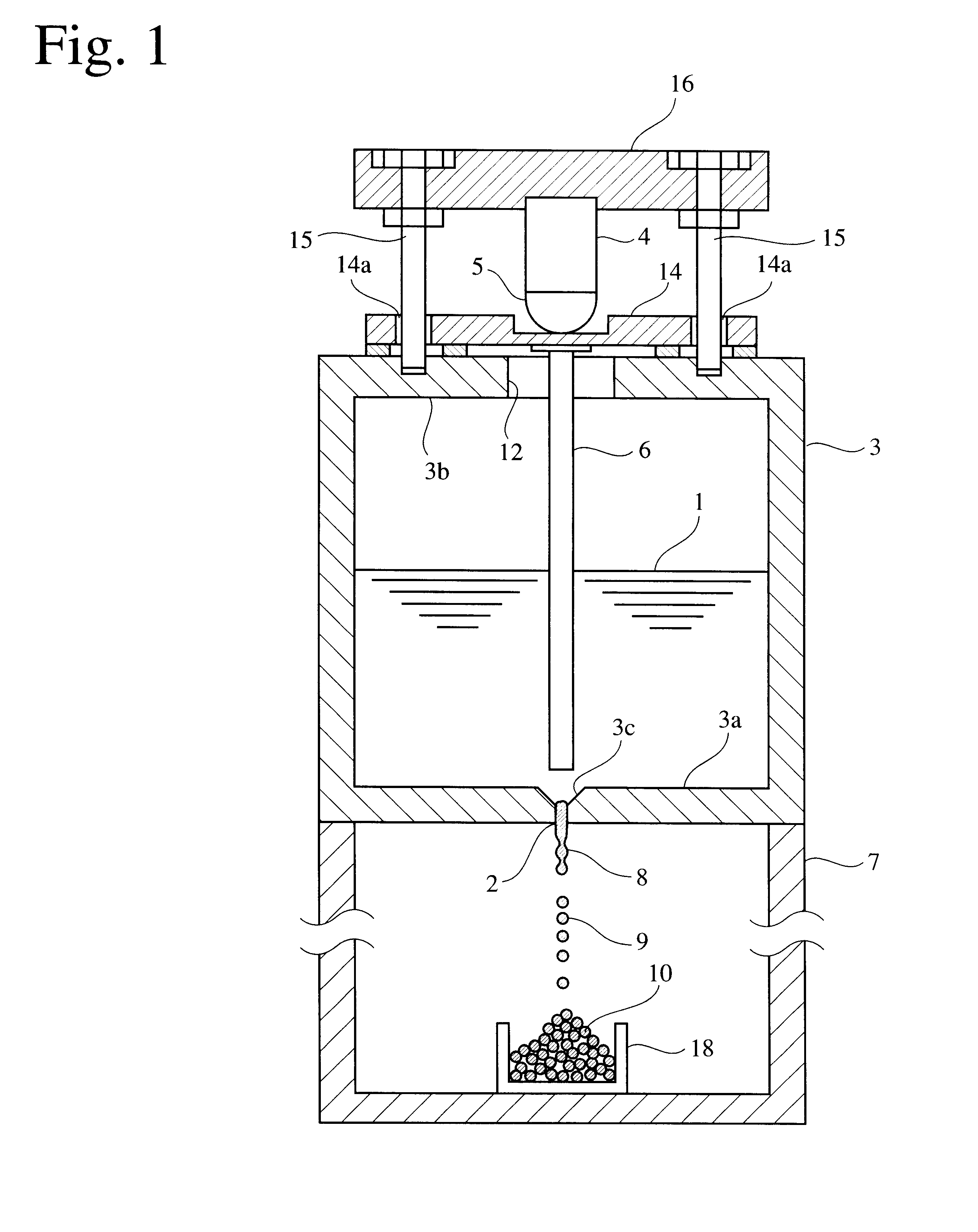
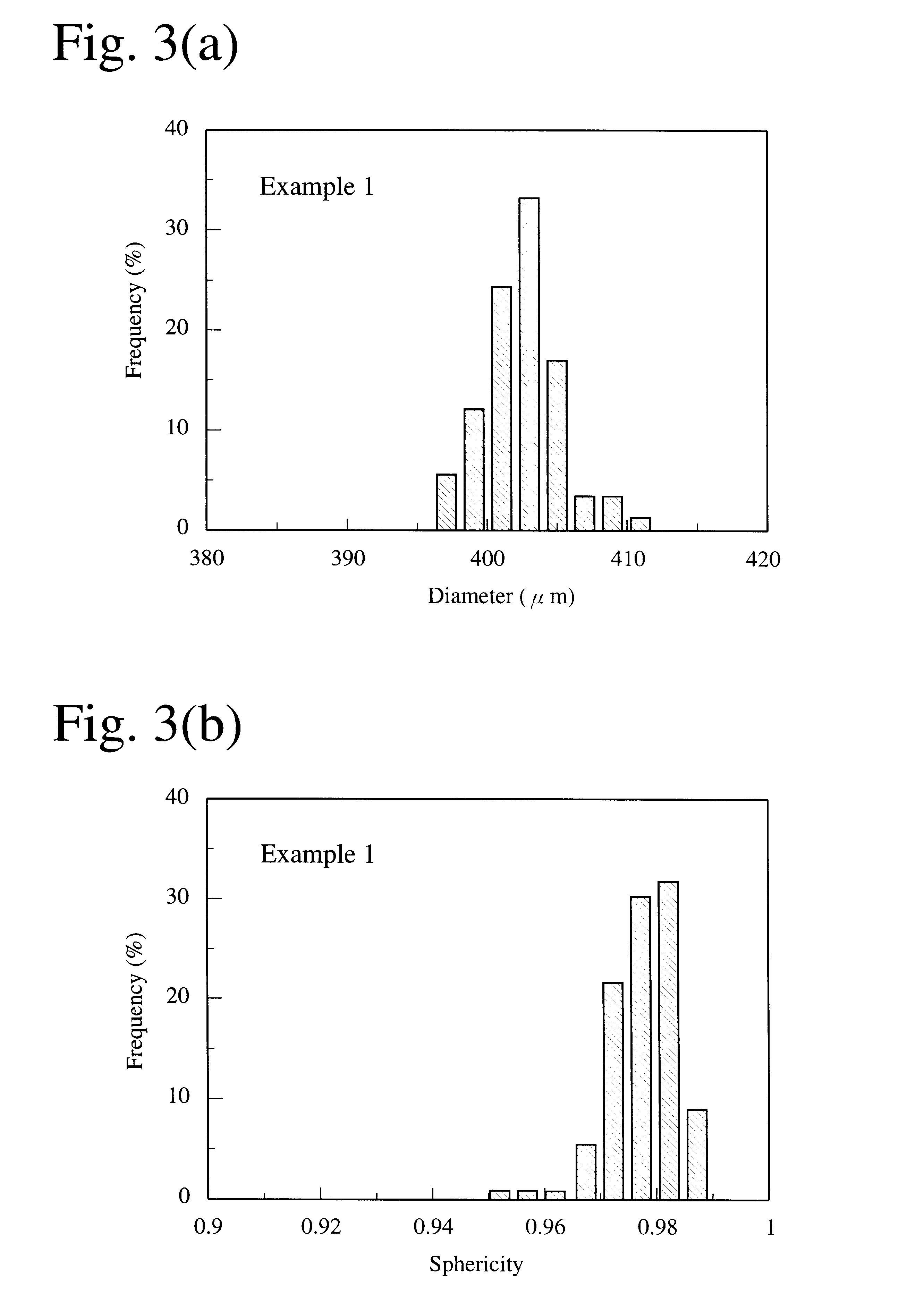
The solder balls of 600 .mu.m in diameter having various alloy compositions were produced in the same manner as in EXAMPLE 1 using the apparatus shown in FIG. 1. The chamber 7 was filled with a nitrogen gas atmosphere of 0.15 MPa (gage pressure). 92% of all the resultant solder balls had dimension accuracy within a range of 590-610 .mu.m. As a result of measuring the sphericity (diameter of corresponding circle / maximum diameter) of 20 solder balls having dimension accuracy within a range of 590 -610 .mu.m, the sphericity was 0.98 or more.

5000 solder balls having diameters of 590-610 .mu.m were arbitrarily selected to carry out a rolling test by which the number of solder balls stopping on a slanting plate were counted to evaluate their surface conditions as rollability. The standards of evaluation of rollability were as follows.

.largecircle.: Less than 0.1% of solder balls among all the rolling solder balls stopped on the slope ( good rollability).

.DELTA.: Less than 0.1% of solder b...

example 4

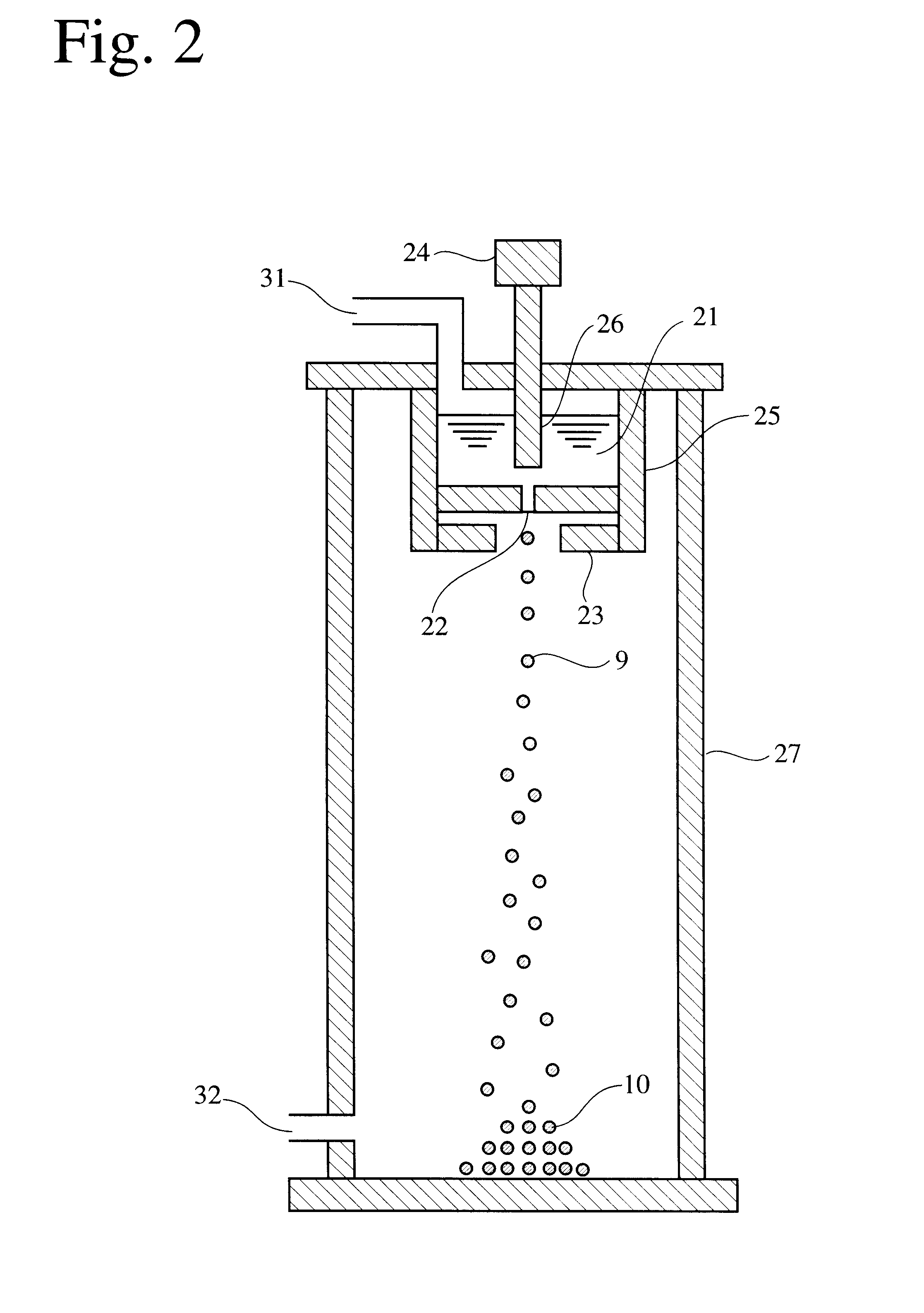
Solder balls of 600 .mu.m in diameter having various alloy compositions were produced under the same conditions as in EXAMPLE 3 using the apparatus shown in FIG. 2, and 300 solder balls thus produced were observed with respect to surface conditions by a scanning-type electro microscope. The surface smoothness of solder balls was evaluated from the scanning-type electron photomicrographs by the following standards.

.largecircle.: Less than 6% of all the solder balls have ragged surface as shown in FIG. 11, and the remaining solder balls have smooth surface as shown in FIG. 10 (solder balls have excellent surface smoothness).

X: 6% or more of all the solder balls have ragged surface as shown in FIG. 11, and the remaining solder balls have smooth surface as shown in FIG. 10 (solder balls have poor surface smoothness).

5000 solder balls produced under the same conditions as above were evaluated with respect to rollability under the same conditions as in EXAMPLE 3. It should be noted that t...


PUM

PropertyMeasurementUnit
mass %aaaaaaaaaa
mass %aaaaaaaaaa
diameteraaaaaaaaaa

Abstract

A solder ball having a diameter of 1.2 mm or less, a dispersion of a diameter distribution of 5% or less and sphericity of 0.95 or more, an area ratio of the maximum dendrite being 80% or less of a cross section including a center of the solder ball, comprises a first additional element of 0.5-8 mass % of Ag and / or 0.1-3 mass % of Cu, and 0.006-10 mass %, in total, of at least one second additional element selected from the group consisting of Bi, Ge, Ni, P, Mn, Au, Pd, Pt, S, In and Sb, the balance being substantially Sn. The solder ball is produced by a uniform droplet-spraying method comprising the steps of vibrating a melt of a solder alloy in a crucible under pressure to force the melt to drop through orifices of the crucible; permitting the melt dropping through the orifices to become spherical droplets in a non-oxidizing gas atmosphere; and rapidly solidifying them.

Description

The present invention relates to a solder ball for use in bump connection in semiconductor devices, etc., and a method for producing such a solder ball, particularly to a solder ball having high sphericity, smooth surface and high dimension accuracy and a method for producing such a solder ball.PRIOR ARTSolder balls have conventionally been produced by an in-oil spheroidizing method. The in-oil spheroidizing method of solder balls comprises the steps of (1) introducing fine solder pieces cut at a constant interval into an oil bath having a vertical temperature distribution, (2) heating the fine solder pieces to a temperature higher than their melting point in an upper portion of the oil bath so that they are melted to become spherical by their own surface tension, (3) precipitating the molten spherical solder to a bottom portion of the oil bath kept at a temperature lower than the melting point of the solder, and (4) solidifying them and degreasing and washing them.Recently proposed...

Claims


Application Information

Patent Timeline
Patent Type & Authority Patents(United States)
IPC IPC(8): B22F1/00B22F9/06B23K35/26B23K35/02C22C13/00C22C13/02H05K3/34B22F1/065
CPCB22F1/0048B23K35/0244B23K35/262C22C13/00C22C13/02H05K3/3436B22F9/06Y10S75/953B22F2999/00H05K3/3463H05K3/3478H05K2203/041B22F2202/01Y02P70/50B22F1/065
Inventor SATOKUBOI, TAKESHIDATE, MASAYOSHI
Owner DUKSAN HI METAL
Why Eureka
Try Eureka