

Methods for producing enhanced interference pigments
a technology of interference pigments and pigments, which is applied in the field of methods and apparatus for the production of thin interference coatings, can solve the problems of large islands or dots of material being deposited on the base material, continuous coatings are obtained at the expense, and the electron generation rate is enhanced, and the deposition rate is increased. , the effect of enhancing the electron generation ra
Inactive Publication Date: 2003-02-25
JDS UNIPHASE CORP
View PDF73 Cites 66 Cited by
- Summary
- Abstract
- Description
- Claims
- Application Information
AI Technical Summary
Benefits of technology
It is another object of the invention to provide pigment compositions that exhibit enhanced color effects and hiding power.
In addition to the structural and optical properties of the coatings produced with the apparatus, systems and methods of this invention, the dry processes of this invention are more environmentally friendly and comparatively less hazardous than conventional techniques because the processes of this invention do not produce waste solutions that must be disposed of following the coating processes. In addition, the methods of this invention do not require the incorporation of catalytic ions such as palladium or tin ions that are necessary elements in electrochemical wet chemical methods. The use of such ions may disadvantageously prevent the subsequent use of the manufactured pigments in various consumer products.
Problems solved by technology
Electroless deposition methods and pyrolytic methods, however, produce large islands or dots of the material being deposited on the base material.
Consequently, continuous coating is obtained at the expense of depositing enough coating material to sufficiently coat the gaps between such large islands or dots.
This extensive deposition leads in turn to a thick coating which, because of its thickness, does not generate the best chromatic colors.
In short, these conventional methods produce thick coalescence layers.
When the preservation of the surface structure of the material that is being coated is desired, a thick coalescence layer has the disadvantageous feature of significantly altering such underlying surface structure.
Chemical methods of deposition and electroless plating methods are typically limited to materials that involve hydrocarbons (liquid or gases), to organometallic compounds, and to metals, such as silver or nickel, that can readily be deposited by electroless processes.
Chemical methods of deposition and electroless plating methods typically generate solutions that must be disposed of, and some of these methods rely on catalytic substances that are incorporated into the pigments to an extent such that it prevents the use of the pigment in certain applications in various consumer products such as cosmetics.
Method used
View moreImage
Smart ImageViewing Examples

Examples
example 1
Gold Pearl interference pigment was first washed in acetone and dried in an air oven. The dried pigment was then placed in a cooled dish placed in a vacuum chamber pumped to a pressure of about 1.multidot.10.sub.-4 Torr and subjected to DC magnetron coating of chromium in an Ar pressure of about 2.5.multidot.10.sup.-3 Torr.
example 2
Super Green Pearl pigment was similarly washed and dried as described in Example 1. It too was exposed to sputter deposition of chromium while being subjected to vibrational movement.
example 3
Violet Pearl pigment was treated as described in Example 1. It was also sputter coated with chromium.
Login to View More PUM
| Property | Measurement | Unit |
|---|---|---|
| Thickness | aaaaa | aaaaa |
| Thickness | aaaaa | aaaaa |
| Angle | aaaaa | aaaaa |
Abstract
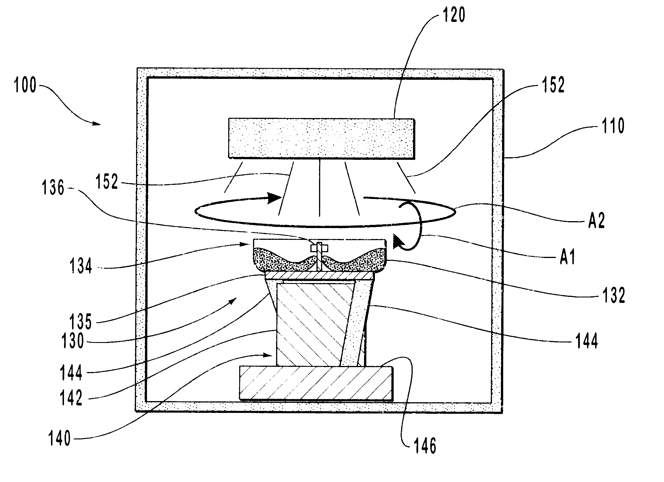
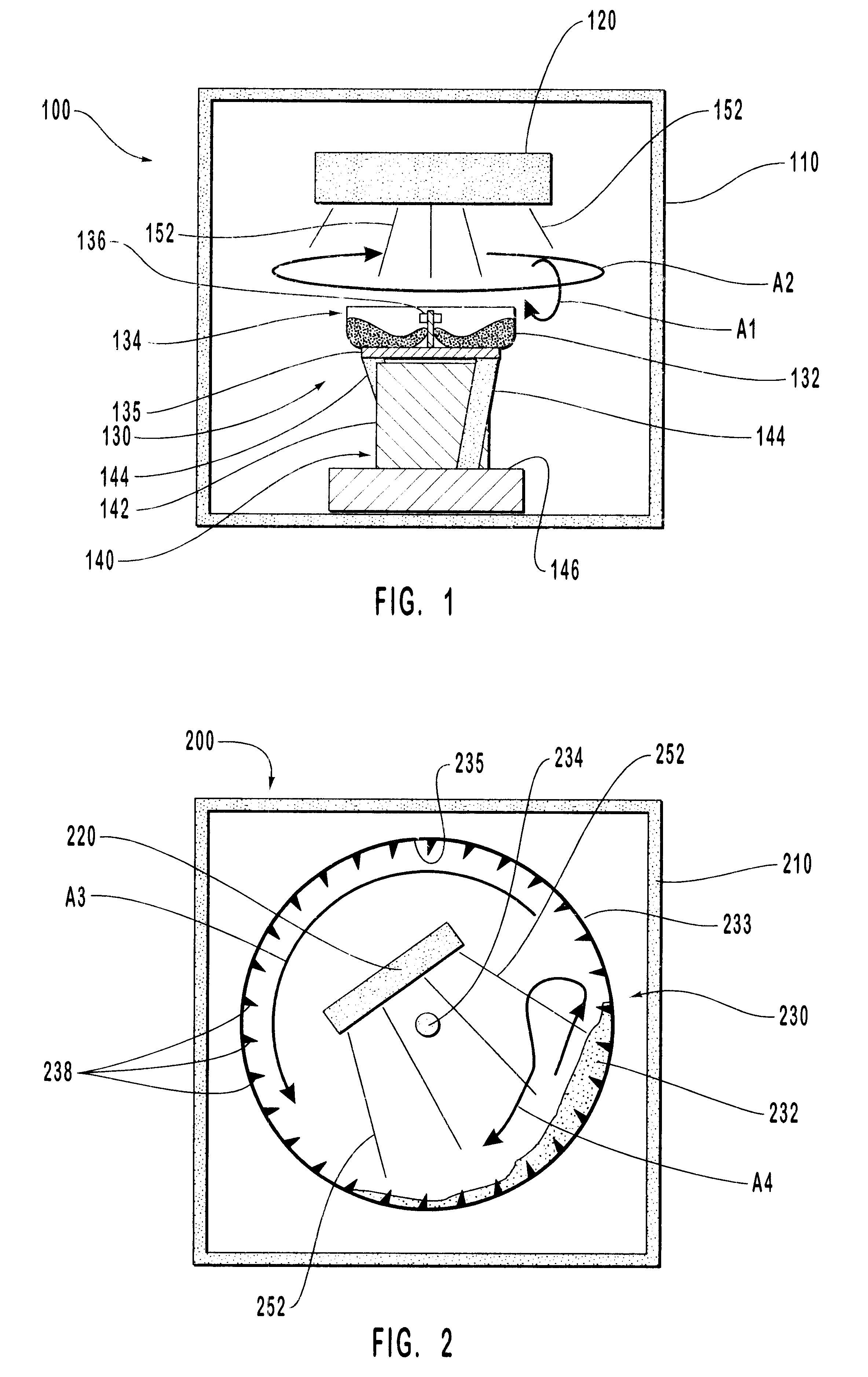
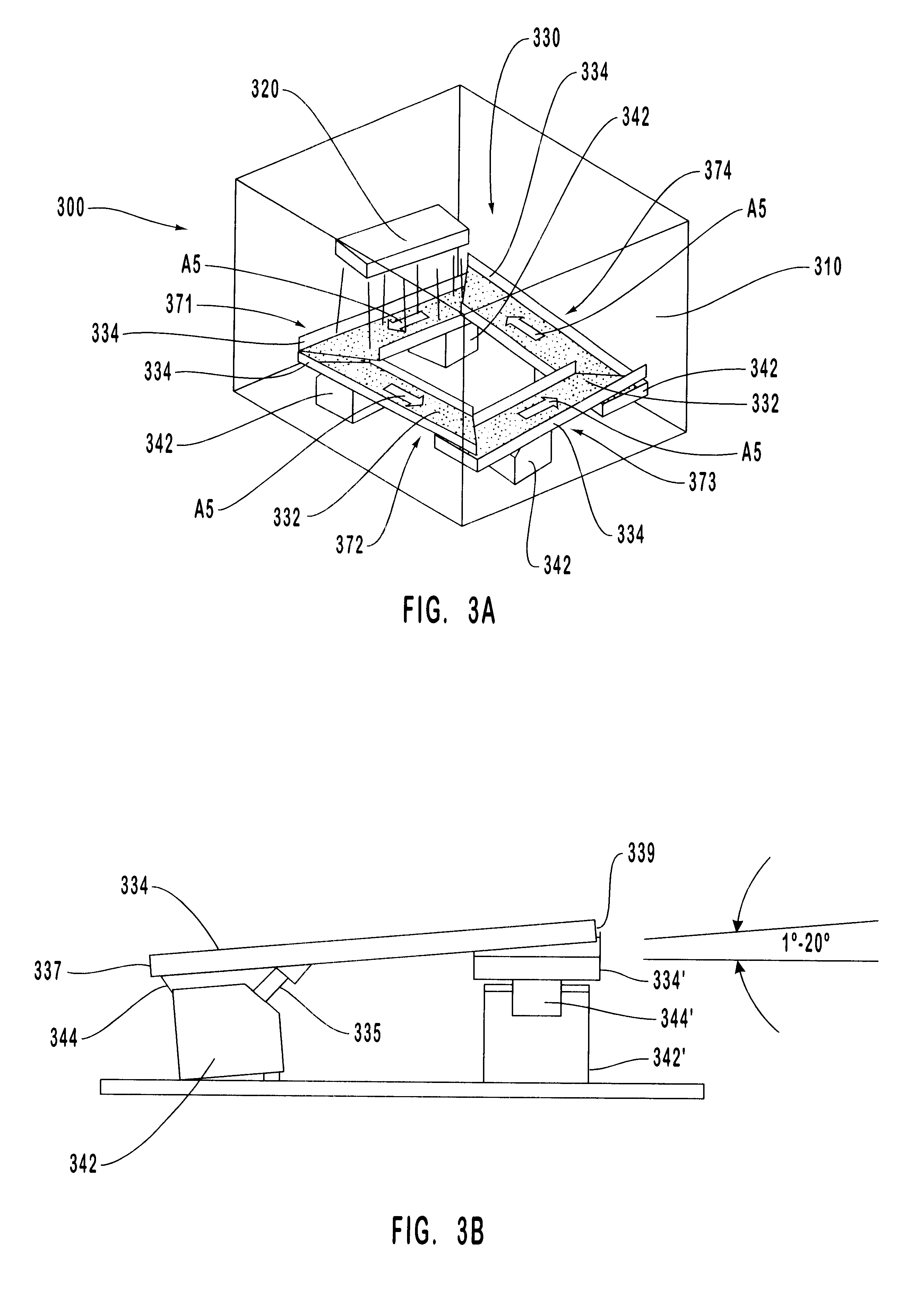
Methods and apparatus are provided for uniformly depositing a coating material from a vaporization source onto a powdered substrate material to form a thin coalescence film of the coating material that smoothly replicates the surface microstructure of the substrate material. The coating material is uniformly deposited on the substrate material to form optical interference pigment particles. The thin film enhances the hiding power and color gamut of the substrate material. Physical vapor deposition processes are used for depositing the film on the substrate material. The apparatus and systems employed in forming the coated particles utilize vibrating bed coaters, vibrating conveyor coaters, or coating towers. These allow the powdered substrate material to be uniformly exposed to the coating material vapor during the coating process.
Description
1. The Field of the InventionThe present invention is related generally to thin film optical coatings for producing interference pigments. More specifically, the present invention is related to methods and apparatus for producing thin interference coatings in the form of thin coalescence films on pigment particles which exhibit enhanced colorant effects and hiding power.2. The Relevant TechnologyInterference pigments and colorants have been used to provide a colored gloss in substances such as cosmetics, inks, coating materials, ornaments and ceramics. Typically, a silicatic material such as mica, talc or glass is coated with a material of high refractive index, such as a metal oxide, and a layer of metal particles is further deposited on top of such highly refractive material. Depending on the type and the content of the highly refractive material, different types of gloss and refractive colors are produced.Thin film flakes having a preselected single color have been previously pro...
Claims
Login to View More Application Information
Patent Timeline
 IPC IPC(8): C09C1/00C09C3/06C09D5/36C23C14/50C23C14/22
CPCC23C14/50C09C1/0015C09C1/0021C09C3/063C09D5/36C23C14/223Y10T428/2911C01P2004/20C01P2006/60C01P2006/63C01P2006/64C01P2006/65C01P2006/66C09C2200/102C09C2200/1058C09C2200/1087C09C2200/24C09C2200/306C09C2220/20Y10T428/2996Y10T428/2991Y10T428/2993C01P2004/03
InventorPHILLIPS, ROGER W.RAKSHA, VLADIMIR
OwnerJDS UNIPHASE CORP