Differential time domain spectroscopy method for measuring thin film dielectric properties

a technology of dielectric properties and time domains, applied in the direction of phase-affecting property measurement, instruments, measurement devices, etc., can solve the problems of difficult extraction, time-consuming, difficult to obtain the visible small phase shift in the waveform under realistic experimental conditions, etc., and achieve the effect of reducing the minimum measurable thickness

Inactive Publication Date: 2003-04-29
RENESSELAER POLYTECHNIC INST
View PDF15 Cites 53 Cited by
  • Summary
  • Abstract
  • Description
  • Claims
  • Application Information

AI Technical Summary

Benefits of technology

In conventional TDS methods, .gamma..sub.diff (.omega.) cannot typically be reduced by increasing the dynamic range of the reference signal because increasing the dynamic range does not decrease .gamma..sub.ref (.omega.). Accordingly, for conventional TDS methods, the noise percentage in E.sub.diff (.omega.) is bigger than in E.sub.ref (.omega.) by a factor of 2.DELTA. / .phi.(.omega.) that is always much larger than 1 for a thin film. In the method of this invention, however, .gamma..sub.diff (.omega.) can be as small as .gamma..sub.ref (.omega.), provided that there is a strong THz signal. In this sense, the method of this invention converts the large dynamic range into better signal-to-noise ratio.
The higher the dynamic range of the system, the stronger the differential signal E.sub.diff (t). Thus, the minimum measurable thickness of a free-standing film depends only on the system dynamic range. For thin film 42 on substrate 40, the minimum measurable thickness d depends on the uniformity of substrate 40 and the uniformity of thin film 42. If substrate 40 or thin film 42 is not uniform, this also contributes to the differential signal. For a THz system with an amplified laser having a dynamic range greater than 10.sup.6, the uniformities of substrate 40 and thin film 42 are typically the ultimate factors that limit the minimum measurable thickness of the thin film. All solid-state laser systems provide maximum stability for reduction of noise effects.
Thus, the method of this invention greatly reduces the minimum measurable thickness over existing technology and is capable of providing dielectric constant measurement of sub-micron films at frequencies below 10 GHz.

Problems solved by technology

For a film much thinner than the wavelength used for measurement, the visibility of the small phase shift in the waveform is difficult to obtain under realistic experimental conditions.
Under most experimental conditions, this extraction is often difficult due to the experimental uncertainty between two separate measurements.
That method requires measurements to be taken at multiple angles of reflection, however, which can be time consuming.

Method used


Image

  • Differential time domain spectroscopy method for measuring thin film dielectric properties
  • Differential time domain spectroscopy method for measuring thin film dielectric properties
  • Differential time domain spectroscopy method for measuring thin film dielectric properties

Examples


example

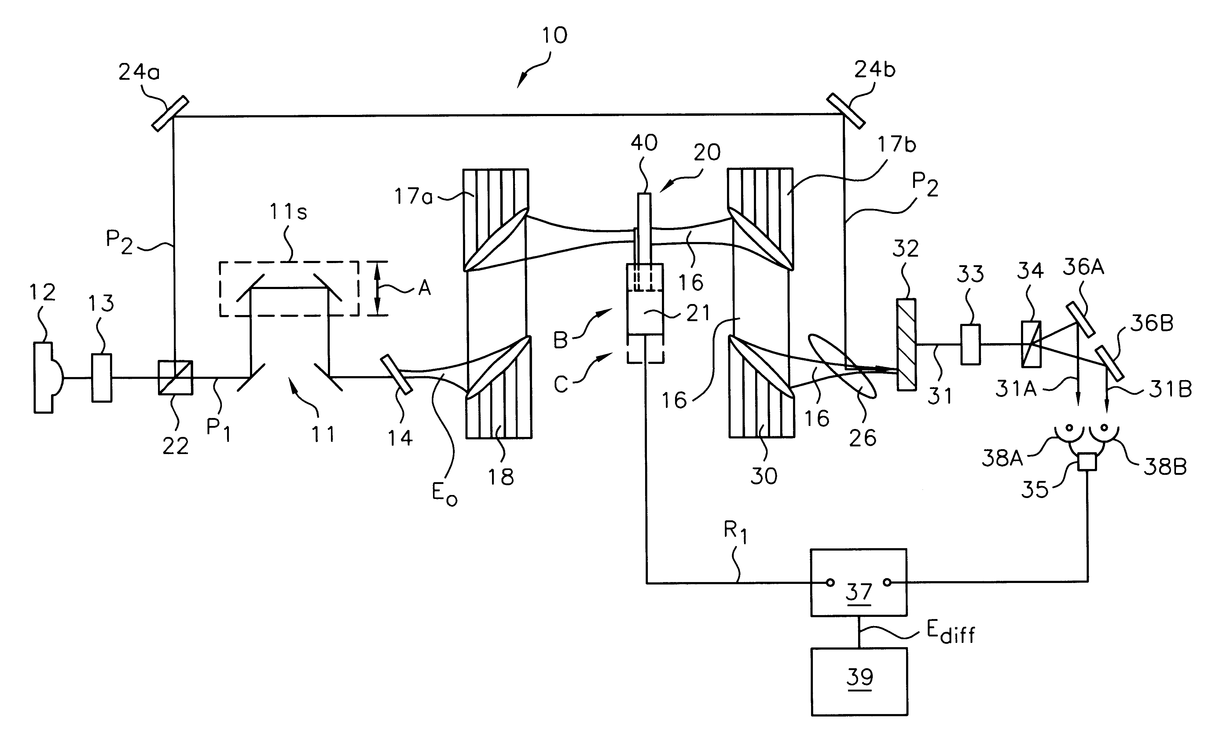
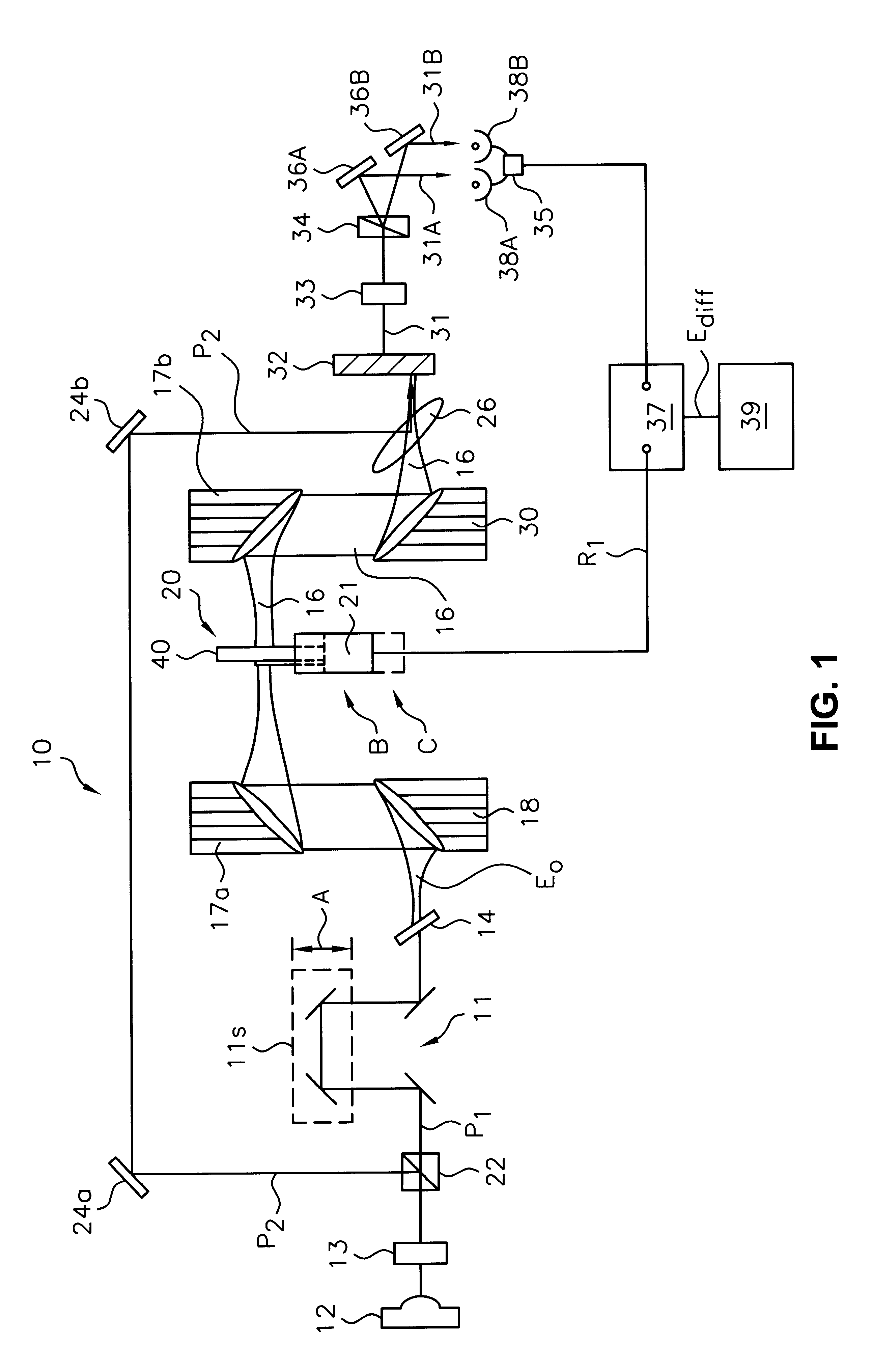
The reference waveform and the differential waveform at 0.7-1.2 THz for a free standing parylene-N (Pa-N) film with a thickness of 1.8 microns were derived using the method of the present invention. For this example, a model Coherent Rega 9000 mode-locked titanium:sapphire laser providing laser pulses with 800 nm central wavelength, 120 fs laser pulse duration, and 250 kHz repetition rate was used. A 2 mm thick ZnTe crystal was used as the THz emitter via optical rectification. A galvanometer adapted to move the sample in and out of the pulse path at a frequency of 16 Hz was also used.

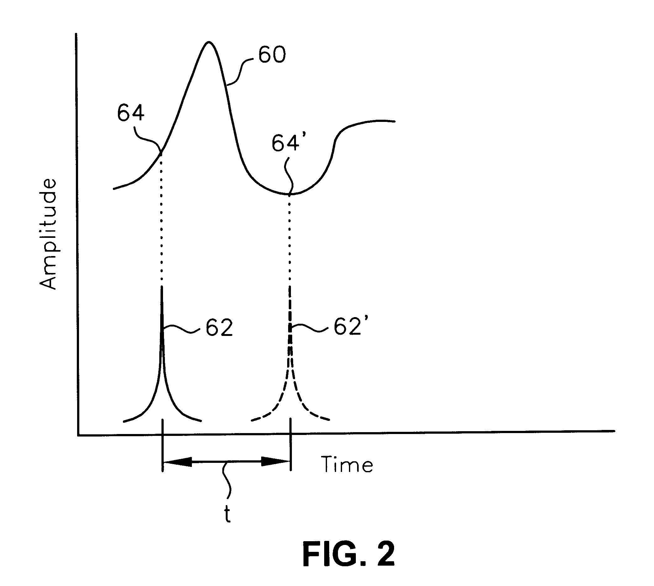
A comparison of typical reference and differential waveforms in the 0.7-1.2 THz frequency range are plotted in FIG. 4. The differential signal is much smaller than the reference signal but is still measured with good signal-to-noise ratio. FIG. 5 shows the refractive index calculated from the experimental data using Equations (7) and (9). FIG. 5 shows the results from four repeated measurements, with ...


PUM

PropertyMeasurementUnit
frequencyaaaaaaaaaa
thicknessaaaaaaaaaa
vibration distanceaaaaaaaaaa

Abstract

A non-contact, free-space method for determining the index of refraction of a thin film at a desired angular frequency. The method includes generating an input desired-frequency pulse and an optically detectable probe pulse. The thin film is moved in and out of the path of the input pulse, creating an output pulse that alternates between a transmitted signal, created when the film intercepts the input pulse path, and a reference signal, created when the sample is outside the input pulse path. The output pulse modulates the probe pulse, which is then detected with a photo detector, and the difference between the transmitted signal and the reference signal is calculated. The above steps are repeated over a plurality of delay times between the input pulse and the probe pulse until a complete field waveform of the differential signal is characterized. The index of refraction is calculated as a function of a ratio between the differential signal for the thin film and the reference signal. A complete field waveform of the reference signal may be characterized by repeating the above steps for a reference plate identical to the sample except having a non-transmissive film instead of the thin, transmissive film.

Description

The present invention relates generally to measurement of dielectric properties of thin films on substrates and, more specifically, to determination of the index of refraction and the dielectric constant of a thin polymer film on a substrate in the gigahertz (GHz) to terahertz (THz) frequency range.In modern microcircuits, the high-frequency capacitance of interlevel dielectrics is a critical parameter that must be understood for realization of high-speed (clock speed>1 GHz) electronic devices. The characterization of the high-frequency dielectric properties of interlevel dielectrics is thereby crucial, particularly in the gigahertz (GHz) to terahertz (THz) range. To bridge electronic and optical gaps formerly encountered in the measurement of the dielectric constant in the GHz-THz frequency range, time-domain spectroscopy (TDS) techniques that incorporate ultrashort laser pulses have been developed in recent years for microcircuit test devices.For characterization of low dielect...

Claims


Application Information

Patent Timeline
Patent Type & Authority Patents(United States)
IPC IPC(8): G01N21/41
CPCG01N21/41G01N21/3563G01N21/3586
Inventor JIANG, ZHIPINGLI, MINGZHANG, XI-CHENG
Owner RENESSELAER POLYTECHNIC INST
Why Eureka
Try Eureka