Luminescence device, display apparatus and metal coordination compound

a technology of metal coordination compound and light source, which is applied in the direction of group 3/13 element organic compound, group 5/15 element organic compound, natural mineral layered product, etc., can solve problems such as luminescent deterioration

Inactive Publication Date: 2004-11-23
CANON KK
View PDF9 Cites 100 Cited by
  • Summary
  • Abstract
  • Description
  • Claims
  • Application Information

AI Technical Summary

Problems solved by technology

However, the above-mentioned organic EL devices utilizing phosphorescence have accompanied with a problem of luminescent deterioration particularly in an energized state.

Method used


Image

  • Luminescence device, display apparatus and metal coordination compound
  • Luminescence device, display apparatus and metal coordination compound
  • Luminescence device, display apparatus and metal coordination compound

Examples


examples 11-16

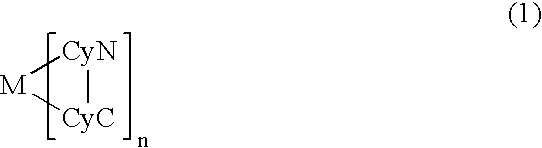
In these examples, metal coordination compounds of formula (1) (Compounds 11-16) were used in respective luminescence layers for Examples 11-16, respectively. ##STR12## ##STR13##

Each of luminescence devices having a structure shown in FIG. 1C were prepared in the following manner.

On a glass substrate (transparent substrate 15), a 100 nm-thick film (transparent electrode 14) of ITO (indium tin oxide) was formed by sputtering, followed by patterning to have an (opposing) electrode area of 3 mm.sup.2.

On the ITO-formed substrate, three organic layers and two metal electrode layers shown below were successively formed by vacuum (vapor) deposition using resistance heating in a vacuum chamber (10.sup.-4 Pa).

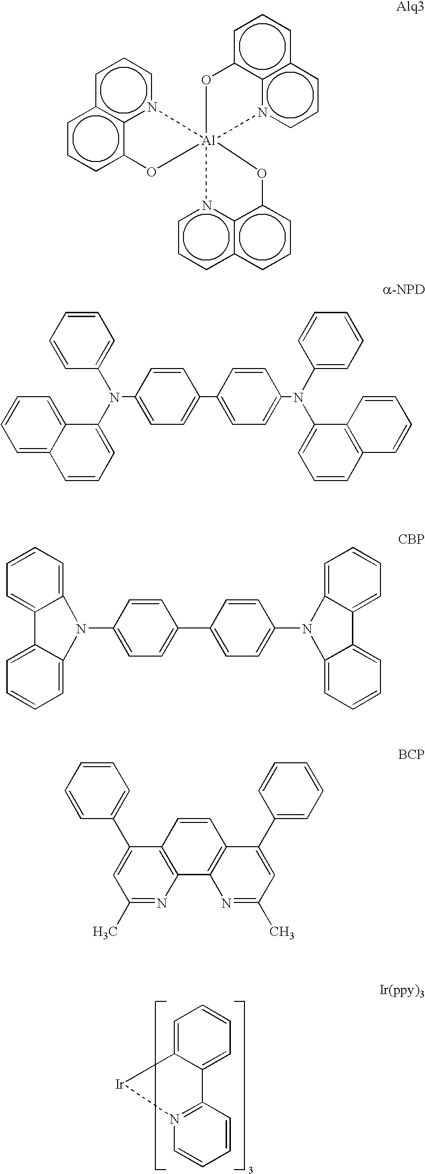
Organic layer 1 (hole transport layer 13) (40 nm): .alpha.-NPD

Organic layer 2 (luminescence layer 12) (20 nm): mixture of CBP: metal coordination compound of formula (1) (93:7 by weight)

Organic layer 3 (exciton diffusion prevention layer 17) (10 nm): BCP

Organic layer 4 (electron transpo...

example 17

Synthesis of Compound 11

##STR15##

In a 200 ml-four necked flask, 100 ml of glycerol was placed and heat-stirred for 2 hours at 130-140.degree. C. while supplying nitrogen gas therein in the form of bubbles, followed by cooing to 100.degree. C. by standing. To glycerol, 1.94 g (12.00 mM) of 2-(2-thienyl)pyridine and 1.00 g (2.0 mM) of Iridium (III) acetylacetonate were added, followed by heat-refluxing for 8 hours under stirring in nitrogen gas stream.

After the reaction, the reaction mixture was cooled to room temperature and poured into 600 ml of 1N--HCl. The resultant precipitate was recovered by filtration and washed with water, followed by drying for 4 hours at 100.degree. C. under reduced pressure and purification by silica gel column chromatography (eluent: chloroform) to obtain 0.38 g of Iridium (III) tris[2-(2-thienylphenyl)pyridine) (red powder) (Yield: 28.2%).

example 18

Synthesis of Compound 12

##STR16##

In a 1 liter-three necked flask, 33.70 g (185.8 mM) of 2-chloro-5-trifluoromethylpyridine, 23.77 g (185.8 mM) of thiophene-2-bronic acid, 200 ml of toluene, 100 ml of ethanol and 200 ml of 2M-sodium carbonate aqueous solution were placed and stirred in a nitrogen gas stream at room temperature. Under stirring, to the mixture, 6.66 g (5.76 mM) of tetrakis (triphenylphosphine) palladium (0) was added, followed by heat-refluxing for 5 hours under stirring in nitrogen gas stream.

After the reaction, the reaction mixture was cooled, followed by extraction with cool water and toluene. The organic layer was washed with water until the system showed neutral, followed by distilling off of the solvent under reduced pressure to obtain a residue. The residue was purified by silica gel column chromatography (eluent: toluene / hexane=2 / 1) and recrystallized from ethanol to obtain a pale yellow crystal. The crystal was purified by alumina column chromatography (eluent...


PUM

PropertyMeasurementUnit
emission spectrum peak wavelengthaaaaaaaaaa
dipole momentaaaaaaaaaa
thicknessaaaaaaaaaa

Abstract

A luminescence device that has an organic compound layer disposed between a pair of electrodes. This organic compound layer contains a metal coordination compound represented by the following formula (1)wherein M is Ir, Rh or Pd; n is 2 or 3; CyN is a substituted or unsubstituted cyclic group containing a nitrogen atom connected to M and capable of containing another nitrogen atom and / or sulfur atom; and CyC is a substituted or unsubstituted cyclic group containing a carbon atom connected to M and capable of containing a nitrogen atom and / or a sulfur atom.

Description

FIELD OF THE INVENTION AND RELATED ARTThe present invention relates to a luminescence device, a display apparatus and a metal coordination compound therefor. More specifically, the present invention relates to a luminescence device employing an organic metal coordination compound having a formula (1) appearing hereinafter as a luminescence material so as to allow stable luminescence efficiency, a display apparatus including the luminescence device and the metal coordination compound adapted for use in the luminescence device.An organic electroluminescence (EL) device has been extensively studied as a luminescence device with a high responsiveness and high efficiency.The organic EL device generally has a sectional structure as shown in FIG. 1A or 1B (e.g., as described in "Macromol. Symp.", 125, pp. 1-48 (1997)).Referring to the figures, the EL device generally has a structure including a transparent substrate 15, a transparent electrode 14 disposed on the transparent substrate 15, a...

Claims


Application Information

Patent Timeline
Patent Type & Authority Patents(United States)
IPC IPC(8): C07F15/00C09K11/06H01L51/05H01L51/30H05B33/14H01L51/50C07D409/04H01L51/00
CPCC07F15/0033C07F15/0073C09K11/06H01L51/0084H01L51/0085H05B33/14C07F15/006Y10S428/917C09K2211/1003C09K2211/1007C09K2211/1011C09K2211/1029C09K2211/1044C09K2211/1092C09K2211/185H01L51/5012H10K85/341H10K85/342H10K50/11
Inventor TSUBOYAMA, AKIRAMIZUTANI, HIDEMASAOKADA, SHINJIROTAKIGUCHI, TAKAOMIURA, SEISHIMORIYAMA, TAKASHIIGAWA, SATOSHIKAMATANI, JUNFURUGORI, MANABU
Owner CANON KK
Why Eureka
Try Eureka