
System and method for measuring physical stimuli using vertical cavity surface emitting lasers with integrated tuning means

a technology of lasers and lasers, applied in the field of systems using vertical cavities and surface emitting lasers, can solve the problems of grating interference, large cost of most solutions, and wide use of such sensors in the marketplace, and achieve the effects of good coherence length, simple manufacturing, and fast tuning speed

Inactive Publication Date: 2004-12-28
KYTON
View PDF25 Cites 30 Cited by
  • Summary
  • Abstract
  • Description
  • Claims
  • Application Information

AI Technical Summary

Benefits of technology

"The patent text describes a new way to create optical sensors using Bragg gratings and a special type of laser called a vertical cavity surface emitting laser (VCSEL). This new method allows for the creation of more affordable and reliable optical sensor systems. The text also explains how the wavelength position of the sensor's reflectance peaks can be used to measure various physical parameters, such as strain, pressure, temperature, and current. The technical effect of this new method is that it combines the benefits of Bragg gratings with the benefits of integrated microelectromechanical systems (MEMS) to create more affordable and reliable optical sensor systems."

Problems solved by technology

Unfortunately, the widespread use of such sensors has generally been restricted in the marketplace because of many well known problems, including the susceptibility of simple, inexpensive sensing systems to optical noise and the great expense of most of the solutions found to overcome said susceptibility.
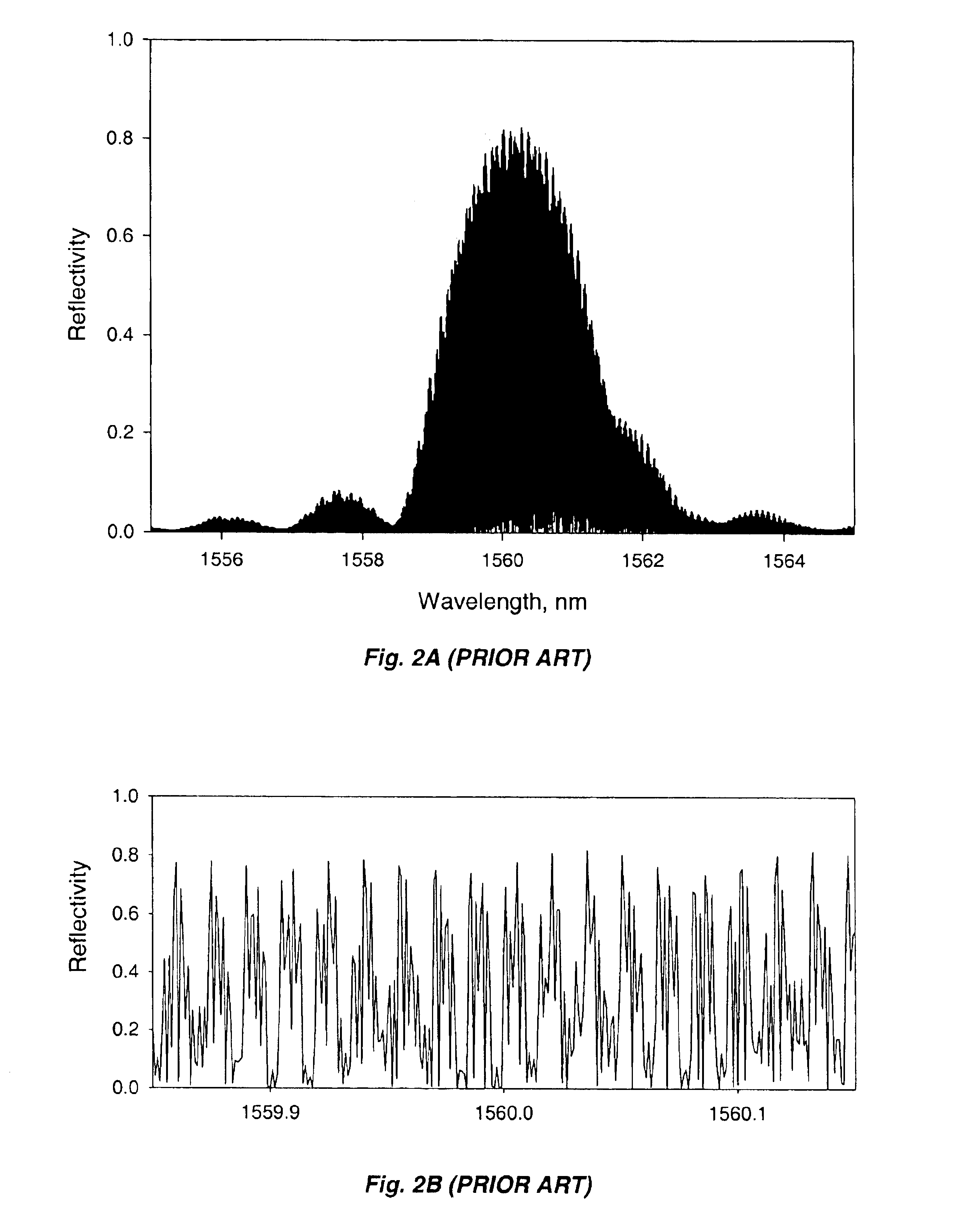
Light reflections caused by the periodic index of refraction pattern in the resulting grating interfere constructively and destructively.
However, such a technique also may suffer from significant limitations.
First, the nature of the laser used can make the detection scheme complex due to the necessity of using complex requirements for wavelength determination.
Second, the accuracy and resolution of the instrument may be far from optimal due to the limited wavelength range of the laser that was specified.
Third, the update rate of such an instrument may be quite slow due to both the slow tuning speed of the laser specified and the large computational overhead from the active wavelength determination scheme used, which in turn limited the accuracy of the instrument.
Fourth, the detection range of these systems may be limited by the short coherence length of the laser.
Fifth, the price of such a system may be very high compared to competitive electronic techniques, due both to the laser and the active wavelength determination scheme used.
Despite the attractiveness of the Froggatt approach, it may be stated that this scheme has not reached wide market acceptance.
This limits critical parameters such as the magnitude of the reflected peak available to the optical sensor, causing lower-than-desirable signal-to-noise ratios.
However, past art approaches are generally too expensive, too slow, too unstable or too inaccurate to have a wide range of practical applications.
Laser diodes tuned with their excitation current, while inexpensive and faster than thermal methods, suffer from narrow tuning wavelength spans and changing optical power, which may limit practical applications to only time division-multiplexed (TDM) Bragg sensors.
The broadband light source method utilizes an inexpensive light source, but generally requires a spectrometer to read the signals (an optical spectrum analyzer may cost as much as $35,000).
Still, spectrometers are temperamental and not well suited to field use.
In addition, such lasers are typically slow to tune, such as 100 nm / sec, and may be even more delicate than spectrometers.
However, with broadband light sources used for interrogation, measurements that are based on light intensity or count interference fringes are very susceptible to optical noise or other technical problems (e.g., losing count of the fringes), to the point of being impractical.
The sole practical, self-calibrating system uses an optical cross-correlating interferometer as a detector, also an expensive technique (see, for example, U.S. Pat. Nos. 5,202,939 and 5,392,117 both issued to Belleville, et al.).
However, the multiplexing of a number of sensors with such a technique (such as required for structural monitoring and many other applications) is impossible as far as is presently known.

Method used


Image

  • System and method for measuring physical stimuli using vertical cavity surface emitting lasers with integrated tuning means
  • System and method for measuring physical stimuli using vertical cavity surface emitting lasers with integrated tuning means
  • System and method for measuring physical stimuli using vertical cavity surface emitting lasers with integrated tuning means

Examples


Embodiment Construction

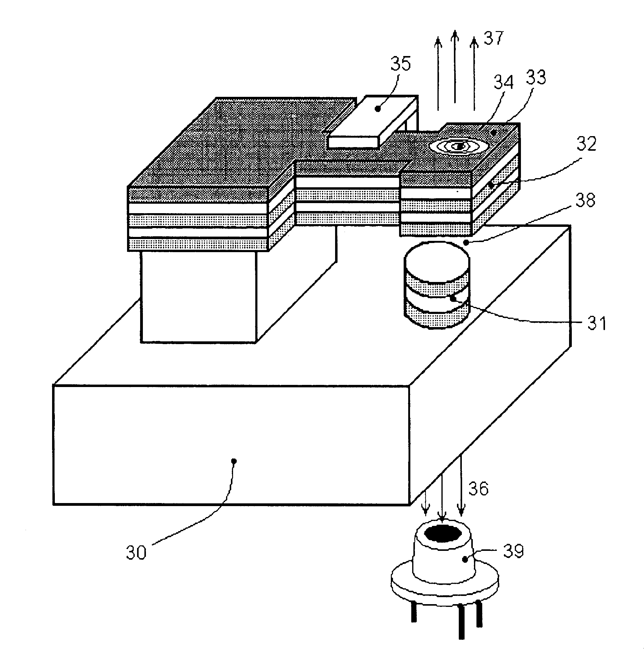
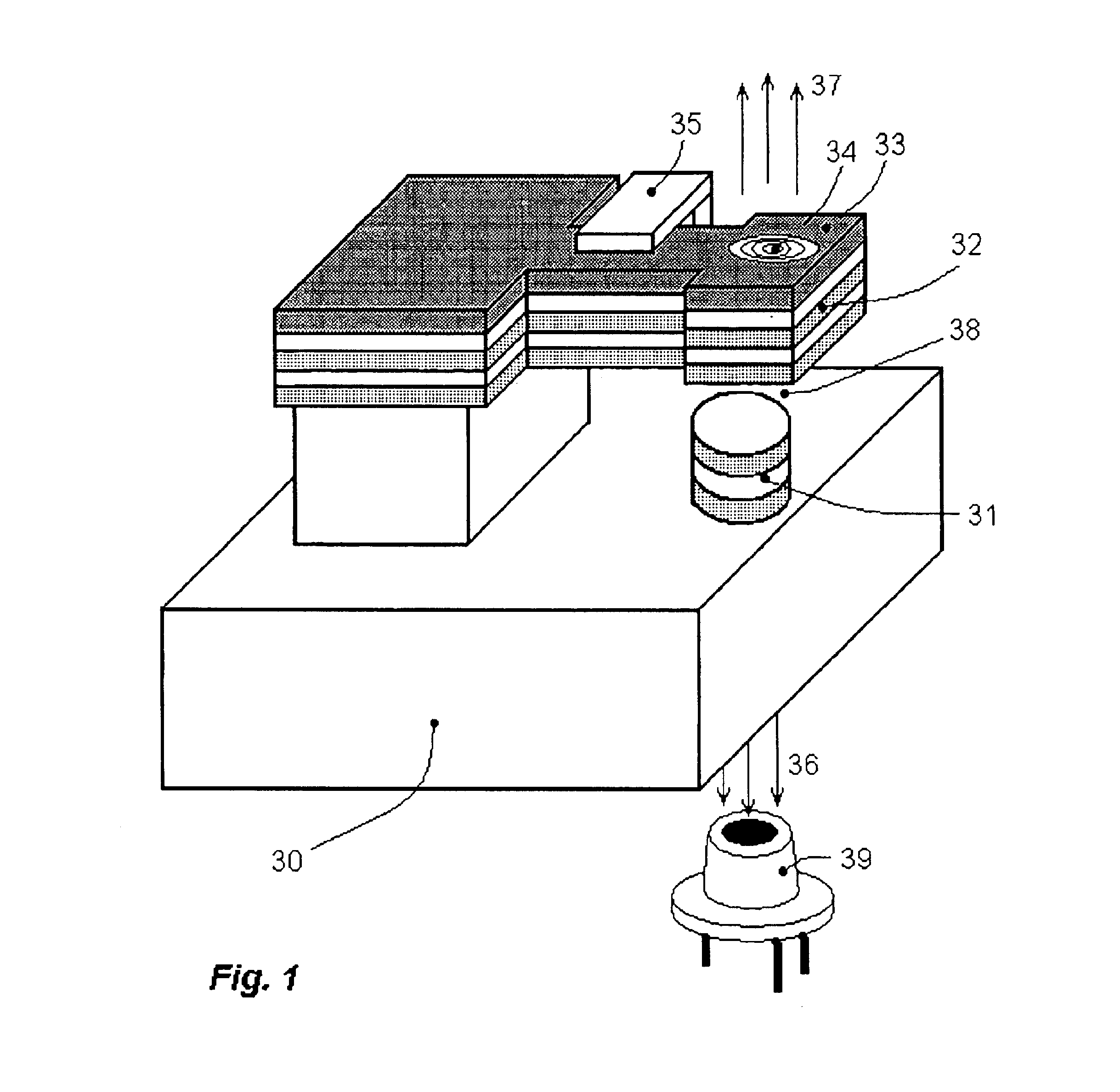
FIG. 1 is an illustrative schematic drawing of an exemplary illustrative VCSEL incorporating one non-limiting example of an integrated MEMS (micro-electromechanical machined system) tuning mechanism in the form of a cantilevered mirror and optional lens. Substrate chip 30 has fabricated upon it, when in wafer form, a multilayer stack of materials forming the light emitting VCSEL 31 and tuning components. Exemplary tuning components may consist of a mirror stack 32, an actuator and structural means 33 that change the tuning cavity length 38, a diffractive optical lens 34 (optional), and a capacitive cantilever position monitor 35 (optional). Light beams may be emitted in directions 36 and / or 37. If either mirror 32 or bottom of stack 31 is opaque, light is emitted only in one direction 37 or 36 respectively. Emission in both directions is possible if both 32 and 31 are partially transparent. This arrangement provides a simple means for optical power monitoring with a photodiode 39 fo...


PUM

PropertyMeasurementUnit
wavelength rangeaaaaaaaaaa
coherence lengthaaaaaaaaaa

Abstract

An optical sensor diagnostic system utilizes a tunable Vertical Cavity Surface Emitting Laser (VCSEL) that incorporates an integrated MEMS tuning mechanism provides variable wavelength light into an optical fiber with improved wavelength scanning speed and greater simplicity of construction. Sensors, such as Bragg gratings, are disposed along the fiber in the light path. Each sensor reflects or transmits light exhibiting a characteristic amplitude and / or phase feature with respect to wavelength, the wavelength position of which is affected by an environmental stimulus imposed thereon. The light reflected or transmitted through each sensor is mixed with light passed through an optical reference path and then converted to an electrical signal by a simple detector and monitored by ciruitry that applies signal processing to the detected power spectral distribution, by this means providing output signals indicative of the environmental stimulus on each sensor.

Description

Not applicable.FIELDThe technology herein relates to systems using vertical cavity, surface emitting lasers (VCSELs), and more particularly to such VCSELs having integrated MEMS (micro-electromechanical) wavelength tuning means to interrogate optical sensors. Still more particularly, the technology herein relates to such systems for use in interrogating fiber and planar Bragg gratings and etalons sensitive to physical stimuli, and to specific system configurations for use with such Bragg grating and etalon sensing devices.BACKGROUND AND SUMMARYFiber optic sensors employing measurement of the shift of wavelength position of a sensor's spectral peculiarity (maximum, minimum or some other function) under the influence of a physical stimulus are well known to those skilled in the art. Examples of such sensors include Bragg grating-based strain, pressure, temperature and current (via the associated magnetic fields) sensors and Fabry-Perot (FP) etalon pressure, temperature and strain sens...

Claims


Application Information

Patent Timeline
Patent Type & Authority Patents(United States)
IPC IPC(8): G01B9/02G01N21/45G02B26/00G01N21/41G02B6/42G02B6/34G01N21/39
CPCG01D5/35316G01K11/3206G01N21/39G01N21/45G02B26/001G02B6/42G02B6/29317G02B6/29358G02B6/4202G02B6/4206G02B6/29319
Inventor KOCHERGIN, VLADIMIRSWINEHART, PHILIP
Owner KYTON
Learn More