Method for producing semiconductor including forming a layer containing at least silicon carbide and forming a second layer containing at least silicon oxygen carbide

a technology of silicon carbide and semiconductor, applied in the direction of coating, metallic material coating process, chemical vapor deposition coating, etc., can solve the problems of short-circuit device failure, silicon carbide barrier layer typically having undesirable characteristics, film instability, etc., to improve current leakage

Inactive Publication Date: 2005-01-04
APPLIED MATERIALS INC
View PDF117 Cites 24 Cited by
  • Summary
  • Abstract
  • Description
  • Claims
  • Application Information

AI Technical Summary

Problems solved by technology

Low k dielectric materials are often porous and susceptible to interlayer diffusion of conductive materials, such as copper, which can result in the formation of short-circuits and device failure.
However, silicon carbide barrier layers typically have had undesirable characteristics, such as unacceptable current leakage, and film instability, such as upon exposure to air.
However, the nitrogen in nitrogen-doped silicon carbide layers can poison photoresist layers deposited on a substrate.

Method used


Image

  • Method for producing semiconductor including forming a layer containing at least silicon carbide and forming a second layer containing at least silicon oxygen carbide
  • Method for producing semiconductor including forming a layer containing at least silicon carbide and forming a second layer containing at least silicon oxygen carbide
  • Method for producing semiconductor including forming a layer containing at least silicon carbide and forming a second layer containing at least silicon oxygen carbide

Examples


example 1

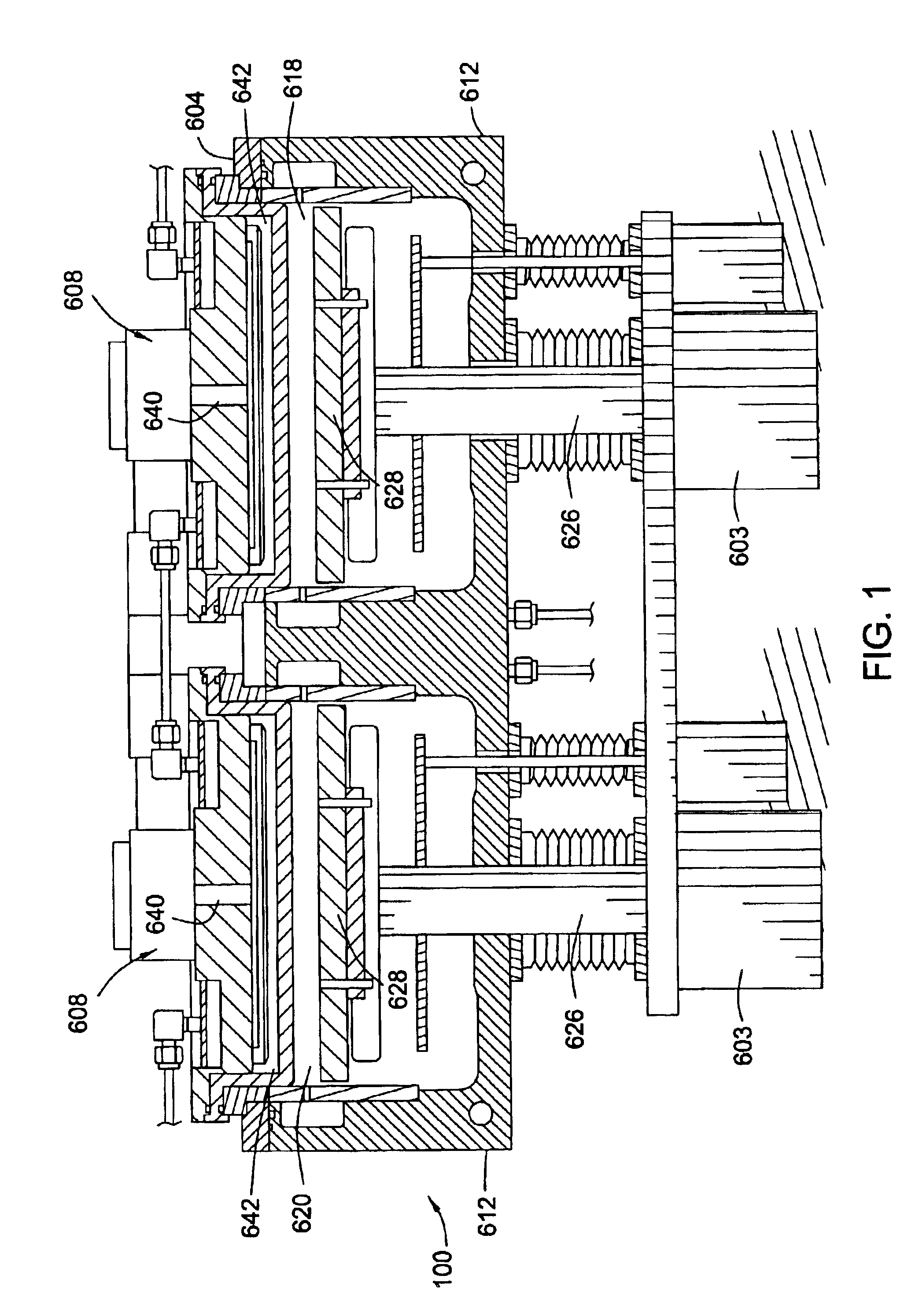
A silicon carbide glue layer was deposited at a chamber pressure of 5 Torr and temperature of 350° C. from gases which were flowed into a plasma processing chamber as follows:

trimethylsilane, at160 sccmethylene, at200 sccmhelium, at200 sccm

The substrate was positioned 400 mil from the gas distribution showerhead and 450 watts of high frequency power at 13.56 MHz was applied to the showerhead for plasma enhanced deposition of a silicon carbide silicon carbide glue layer. The silicon carbide glue layer was deposited at a rate of about 886 Å / min, and had a dielectric constant of about 3.73, a uniformity of about 2.5%, a leakage current of about 2.32×10⁻⁹ A / cm2 at 1 MV / cm, a leakage current of about 3.06×10⁻⁸ A / cm2 at 2 MV / cm, and a breakdown voltage of about 4.47 MV / cm.

example 2

A silicon carbide glue layer was deposited at a chamber pressure of 3 Torr and temperature of 350° C. from gases which were flowed into a plasma processing chamber as follows:

trimethylsilane, at150 sccmethylene, at 200 sccm.

The substrate was positioned 400 mil from the gas distribution showerhead and 600 watts of high frequency power at 13.56 MHz was applied to the showerhead for plasma enhanced deposition of a silicon carbide silicon carbide glue layer. The silicon carbide glue layer was deposited at a rate of about 1255 Å / min, and had a dielectric constant of about 3.81, a uniformity of about 2.7%, a leakage current of about 2.04×10⁻⁹ A / cm2 at 1 MV / cm, a leakage current of about 4.64×10⁻⁸ A / cm2 at 2 MV / cm, and a breakdown voltage of about 4.13 MV / cm.

example 3

A silicon carbide glue layer was deposited at a chamber pressure of 9.5 Torr and temperature of 350° C. from gases which were flowed into a plasma processing chamber as follows:

trimethylsilane, at160 sccmhydrogen, at 200 sccm.

The substrate was positioned 400 mil from the gas distribution showerhead and 450 watts of high frequency power at 13.56 MHz was applied to the showerhead for plasma enhanced deposition of a silicon carbide silicon carbide glue layer. The silicon carbide glue layer was deposited at a rate of about 161 Å / min, and had a dielectric constant of about 3.88, a uniformity of about 5%, a leakage current of about 3.1×10⁻⁹ A / cm2 at 1 MV / cm, a leakage current of about 6.1×10⁻⁸ A / cm2 at 2 MV / cm, and a breakdown voltage of about 4.3 MV / cm.


PUM

PropertyMeasurementUnit
dielectric constantaaaaaaaaaa
flow rateaaaaaaaaaa
sizeaaaaaaaaaa

Abstract

Methods are provided for depositing a silicon carbide layer having significantly reduced current leakage. The silicon carbide layer may be a barrier layer or part of a barrier bilayer that also includes a barrier layer. Methods for depositing oxygen-doped silicon carbide barrier layers are also provided. The silicon carbide layer may be deposited by reacting a gas mixture comprising an organosilicon compound, an aliphatic hydrocarbon comprising a carbon-carbon double bond or a carbon-carbon triple bond, and optionally, helium in a plasma. Alternatively, the silicon carbide layer may be deposited by reacting a gas mixture comprising hydrogen or argon and an organosilicon compound in a plasma.

Description

BACKGROUND OF THE INVENTION1. Field of the InventionEmbodiments of the present invention generally relate to the fabrication of integrated circuits. More specifically, embodiments of the present invention generally relate to processes for depositing barrier layers on a substrate and structures that include the barrier layers.2. Description of the Related ArtSemiconductor device geometries have dramatically decreased in size since such devices were first introduced several decades ago. Since then, integrated circuits have generally followed the two year / half-size rule (often called Moore's Law), which means that the number of devices that will fit on a chip doubles every two years. Today's fabrication plants are routinely producing devices having sub-quarter micron feature sizes, and tomorrow's plants soon will be producing devices having even smaller geometries.In order to further reduce the size of devices on integrated circuits, it has become necessary to use conductive materials ...

Claims


Application Information

Patent Timeline
Patent Type & Authority Patents(United States)
IPC IPC(8): C23C16/56C23C16/40C23C16/30H01L21/70H01L21/02H01L21/768H01L21/312H01L21/316H01L21/311
CPCC23C16/30H01L21/76834C23C16/401C23C16/505C23C16/56H01L21/02126H01L21/02167H01L21/022H01L21/02211H01L21/02274H01L21/31116H01L21/3122H01L21/3148H01L21/31633H01L21/7681H01L21/76825H01L21/76826H01L21/76828H01L21/76829H01L21/76832C23C16/325H01L21/31138H01L21/31144H01L21/312H01L21/3127H01L21/3185H01L21/76807
Inventor YIM, KANG SUBTAM, MELISSA M.SUGIARTO, DIANLANG, CHI-ILEE, PETER WAI-MANXIA, LI-QUN
Owner APPLIED MATERIALS INC
Why Eureka
Try Eureka