Proton-conducting membrane, method for producing the same, and fuel cell using the same

Inactive Publication Date: 2005-03-08
NAT INST OF ADVANCED IND SCI & TECH +2
View PDF11 Cites 27 Cited by
  • Summary
  • Abstract
  • Description
  • Claims
  • Application Information

AI Technical Summary

Benefits of technology

The inventors of the present invention have found, after having extensively studied a variety of electrolyte membranes to solve the above problems, that an innovative organic/inorganic composite membrane can be obtained by including, as the essential components, a selected combination of specific organic material, three-dimensionally crosslinked structure containing a specific silicon-oxygen bond bound

Problems solved by technology

The so-called creep phenomenon occurs as temperature increases from the above level to cause problems, e.g., changed proton-conducting structure in the membrane to prevent the membrane from stably exhibiting the proton-conducting performance, and modification of the membrane to a swollen morphology, or jelly-like morphology to make it very fragile and possibly cause failure of the fuel cell.
Moreover, the sulfonic acid group tends to be eliminated when the membrane of wet morphology is exposed to high temperature, to greatly deteriorate its proton-conducting performance.
The catalyst in service on the anode side may be deactivated by impurities in the hydrogen fuel (e.g., carbon monoxide), a phenomenon known as catalyst poisoning, when it is not sufficiently purified.
This is a serious problem which can determine serviceability of the PEFC itself.
It is a consensus that production of sufficient power is difficult at low temperature, and possible when temperature is increased to, e.g., 150° C. or higher.
Nevertheless, however, its operating temperature is limited to 80° C. at present by the heat resistance consideration of the proton-conducting membrane, as discussed above.
However, the PEFC must be cooled not to be exposed to high temperature of 80° C. or higher, as limited by the resistance of the proton-conducting membrane to heat.
This tends to increase size and weight of the PEFC as a whole, preventing it to fully exhibit its inherent characteristics of compactness and lightness.
In particular, a water-cooling system as the simplest cooling means is difficult to effectively cool the cell, whose maximum allowable operating temperature is set at 80° C. If it is operable at 100° C. or higher, it should be effectively cooled by use of heat of vaporization of water, and water could be recycled for cooling to drastically reduce its requirement, leading to reduced size and weight of the cell.
Nevertheless, however, the proton-conducting membrane having a sufficient proton conductivity and resistance to heat has not been developed so far.
They tend to suffer notable desul

Method used


Image

  • Proton-conducting membrane, method for producing the same, and fuel cell using the same
  • Proton-conducting membrane, method for producing the same, and fuel cell using the same
  • Proton-conducting membrane, method for producing the same, and fuel cell using the same

Examples


example 1

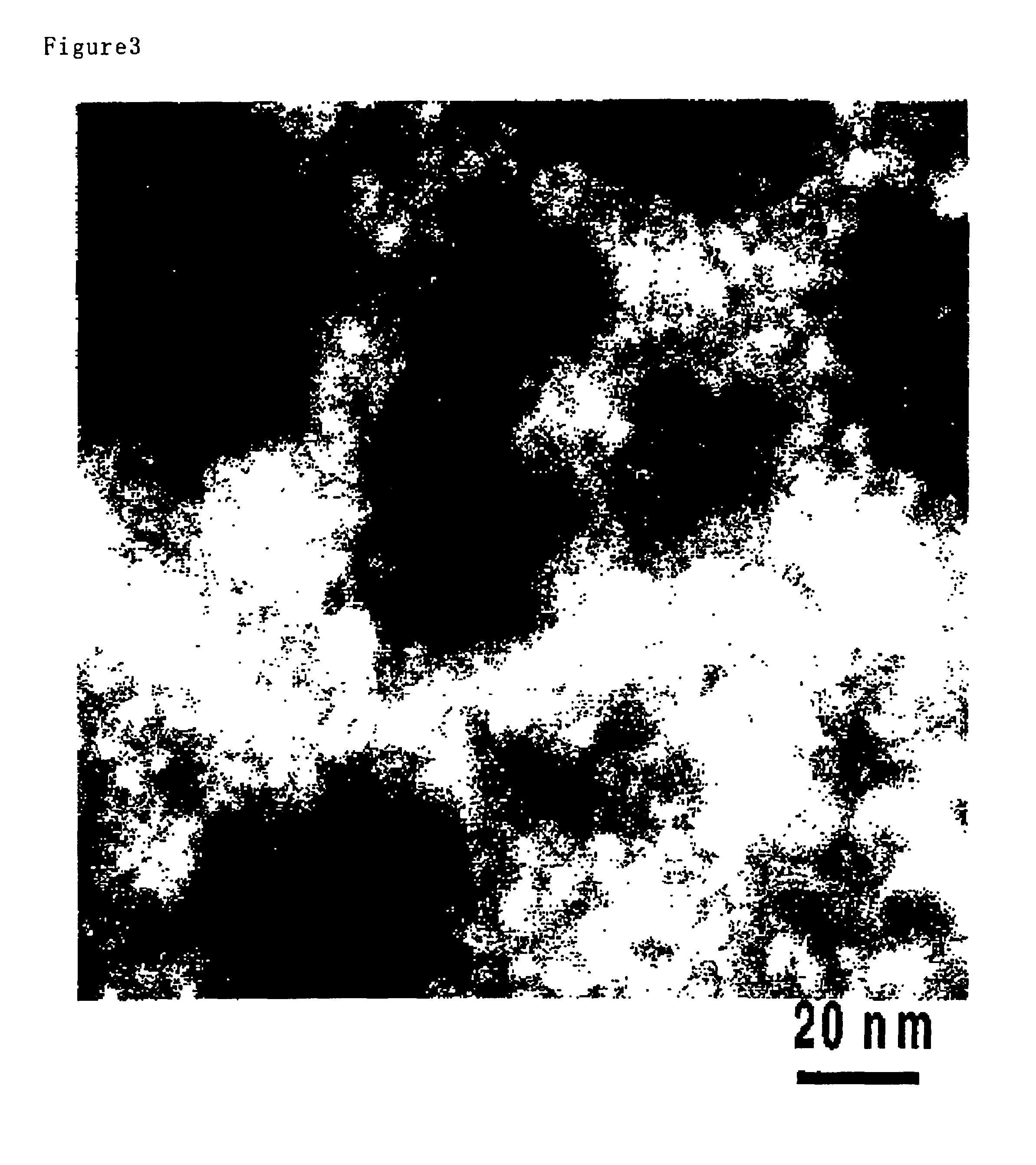
A solution of 0.8 g of 1,8-bis(triethoxysilyl)octane (Gelest Inc.) dissolved in 1.5 g of isopropyl alcohol was prepared. Another solution of 0.7 g of tungstophosphoric acid of n-th hydrate (Wako Pure Chemical Industries) dissolved in 1.5 g of isopropyl alcohol was separately prepared. These solutions were mixed with each other, stirred for several minutes, and poured into a Petri dish of polystyrene (Yamamoto Seisakusho, inner diameter: 8.4 cm), where the mixture was left at room temperature (20° C.) for 15 hours and heated at 60° C. for 10 hours in a saturated steam atmosphere, to prepare the transparent membrane. It was washed in a flow of water at 60° C., before it was analyzed. The evaluation results are given in Table 1.

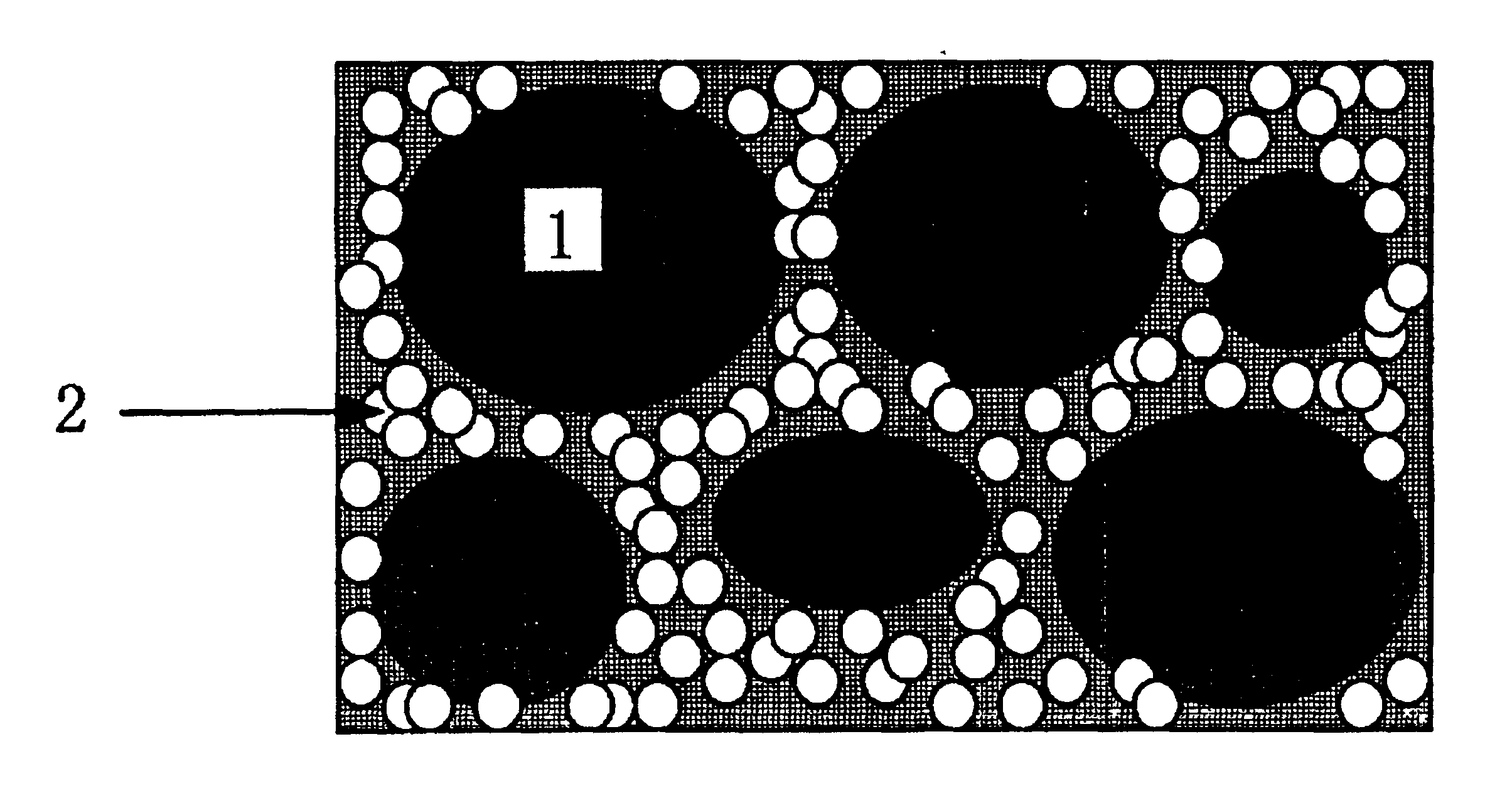
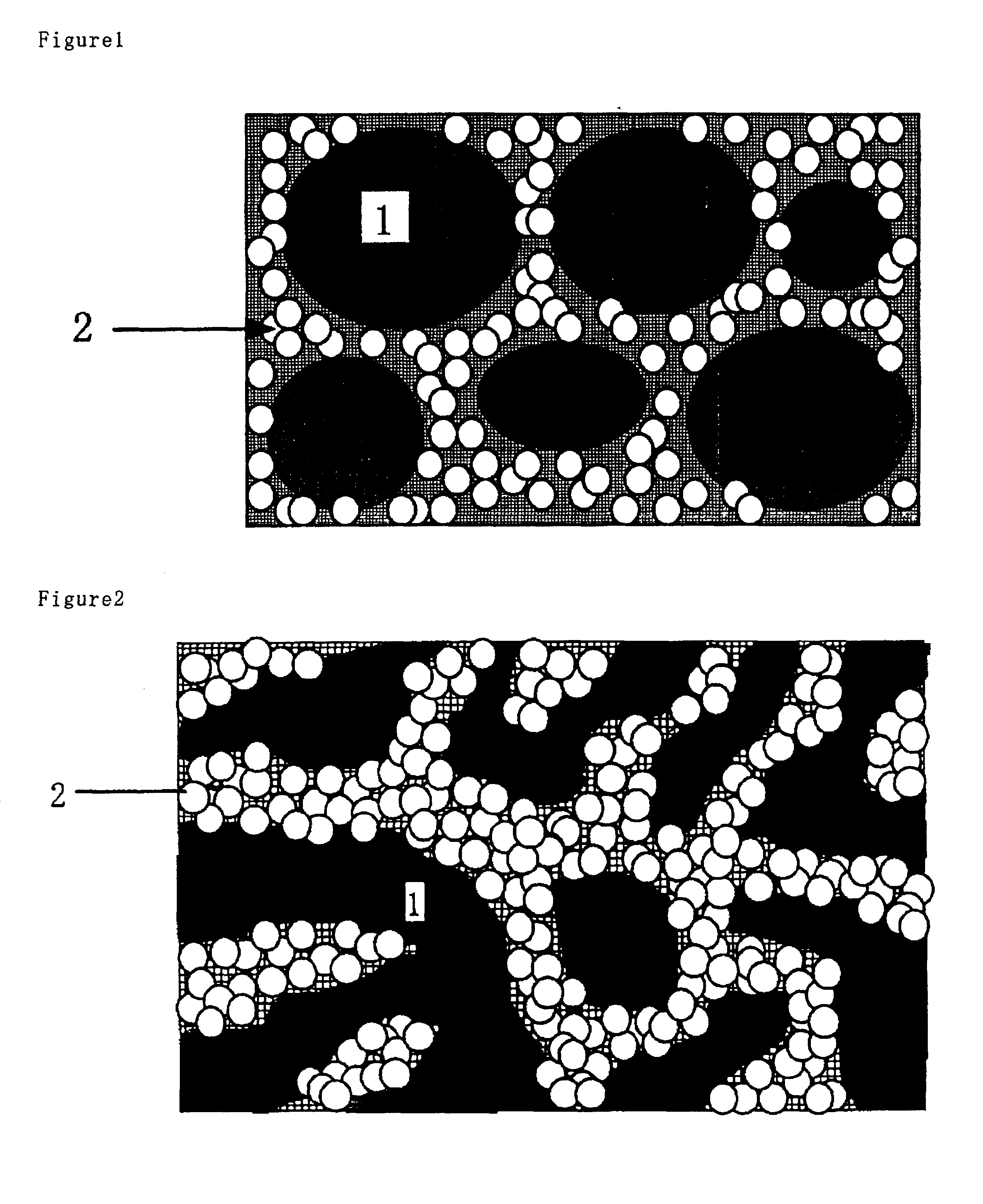
The membrane thus prepared was analyzed by a field emission type electron microscope (e.g., JOEL's JEM-2010F) to produce the Z-contrast microgram, which is given in FIG. 3.

In FIG. 3, the white portion represents the portion derived from tungsten or the like havi...

example 2

The membrane was prepared in the same manner as in EXAMPLE 1, except that 1,8-bis(triethoxysilyl)octane was replaced by 0.8 g of 1,6-bis(trimethoxysilyl)hexane (Gelest Inc.) and 0.8 g of tungstophosphoric acid was used. The evaluation results are given in Table 1.

example 3

(Synthesis of (1,14-bis(triethoxysilyl)tetradecane)

This compound was synthesized in accordance with the method described in detail by, e.g., W. Oviatt et. al. (Chem. Mater., 1993, 5, 943).

A mixture of 25 g of 1,13-tetradecadiene (Aldrich), 44.4 g of triethoxysilane (Shin-Etsu Silicone) and 0.1 mL of 3% xylene solution of a platinum complex of bis((vinyl dimethyl)disiloxane) was stirred at room temperature in a nitrogen atmosphere for 3 days. The resultant reaction mixture was purified by distillation, to obtain 1,14-bis(triethoxysilyl)tetradecane. Its structure was confirmed by NMR.

(Formation of Membrane)

The membrane was prepared in the same manner as in EXAMPLE 1, except that 1,8-bis(triethoxysilyl)octane was replaced by 0.9 g of 1,14-bis(triethoxysilyl)tetradecane and 0.6 g of tungstophosphoric acid was used. The evaluation results are given in Table 1.


PUM

PropertyMeasurementUnit
Temperatureaaaaaaaaaa
Percent by massaaaaaaaaaa

Abstract

A proton-conducting membrane, excellent in resistance to heat, durability, dimensional stability and fuel barrier characteristics, and showing excellent proton conductivity at high temperature and a method for producing the same. A proton-conducting membrane includes a carbon-containing compound and inorganic acid, characterized by a phase-separated structure containing a carbon-containing phase containing at least 80% by volume of the carbon-containing compound and inorganic phase containing at least 80% by volume of the inorganic acid, the inorganic phase forming the continuous ion-conducting paths. The method for producing the above proton-conducting membrane includes steps of preparing a mixture of a carbon-containing compound (D) having one or more hydrolyzable silyl groups and inorganic acid (C), forming the above mixture into a film, and hydrolyzing/condensing the hydrolyzable silyl group contained in the mixture formed into the film, to form a three-dimensionally crosslinked silicon-oxygen structure (A). The above proton-conducting membrane is incorporated in a fuel cell.

Description

TECHNICAL FIELDThis invention relates to a proton (hydrogen ion)-conducting membrane, method for producing the same, and fuel cell using the same, more particularly the proton-conducting membrane, excellent in resistance to heat, durability, dimensional stability and fuel barrier characteristics, and showing excellent proton conductivity at high temperature, method for producing the same, and fuel cell using the same, and, at the same time, the proton-conducting membrane for the direct fuel type fuel cell which is directly supplied with fuel, e.g., methanol or methane, method for producing the same, and fuel cell using the same.BACKGROUND OF THE INVENTIONRecently, fuel cell has been attracting attention as a power generating device of the next generation, which can contribute to solution of the problems related to environments and energy, now having been increasingly becoming serious social problems, because of its high power generation efficiency and compatibility with the environm...

Claims


Application Information

Patent Timeline
IPC IPC(8): B01D69/14B01D69/00B01D71/00B01D71/70C08J5/20C08J5/22H01M8/10C08G77/04H01B1/06H01B13/00H01M8/02
CPCB01D69/141B01D71/70C08J5/2256H01M8/1023H01M8/1037H01M8/1048H01M8/1074H01M8/1044Y02E60/523C08J2383/10Y02E60/522Y02P70/50Y02E60/50H01M8/02B01D69/14111B01D71/701
Inventor HONMA, ITARUNOMURA, SHIGEKISUGIMOTO, TOSHIYANISHIKAWA, OSAMU
Owner NAT INST OF ADVANCED IND SCI & TECH
Why Eureka
Try Eureka