
Method of forming a multi-layered copper bond pad for an integrated circuit

a technology of integrated circuits and bond pads, which is applied in the direction of semiconductor devices, semiconductor/solid-state device details, electrical devices, etc., can solve the problems of complex process, high cost and time consumption, and the formation of non-conductive oxides, etc., to achieve the effect of increasing contact adhesion and increasing bonding yield

Inactive Publication Date: 2005-01-11
MICRON TECH INC
View PDF17 Cites 18 Cited by
  • Summary
  • Abstract
  • Description
  • Claims
  • Application Information

AI Technical Summary

Benefits of technology

The present invention also provides for the passivation of copper surfaces by employing a Ti / Al barrier layer on the copper bond pad that enhances the bonding yield by increasing the contact adhesion between the metal layer and the bonding structure.

Problems solved by technology

Aluminum bond pads are commonly employed on IC dies, but a significant problem with their use is the rapid formation of a tenacious nonconductive oxide on the surface of the metal, even at room temperature.
Nevertheless, the gold plating of the bond pads of a semiconductor die is an elaborate process that can be very difficult, expensive and time consuming.
Many of these materials, however, also form nonconductive oxides, or have poor electrical or thermal conductivity, or a high thermal expansion.
Further, many of these barrier layers exhibit instability at temperatures higher than 400° C. Since a silicon substrate is generally subjected to subsequent steps during the IC fabrication, such as annealing or reflow processes which require temperatures higher than 400° C., there is a need for a barrier layer that is stable at the high temperatures required for subsequent substrate processes steps.

Method used


Image

  • Method of forming a multi-layered copper bond pad for an integrated circuit
  • Method of forming a multi-layered copper bond pad for an integrated circuit
  • Method of forming a multi-layered copper bond pad for an integrated circuit

Examples


Embodiment Construction

In the following detailed description, reference is made to various specific embodiments in which the invention may be practiced. These embodiments are described with sufficient detail to enable those skilled in the art to practice the invention, and it is to be understood that other embodiments may be employed, and that structural, electrical and methodology changes may be made and equivalents substituted without departing from the invention. Accordingly, the following detailed description is not to be taken in a limiting sense and the scope of the present invention is defined by the appended claims.

The term “substrate” used in the following description includes any semiconductor-based structure having an exposed silicon surface in which to form the structure of this invention. The term substrate is to be understood as including silicon-on-insulator, doped and undoped silicon, epitaxial layers of silicon supported by a base semiconductor foundation, and other semiconductor structur...


PUM

PropertyMeasurementUnit
energy levelaaaaaaaaaa
temperaturesaaaaaaaaaa
temperatureaaaaaaaaaa

Abstract

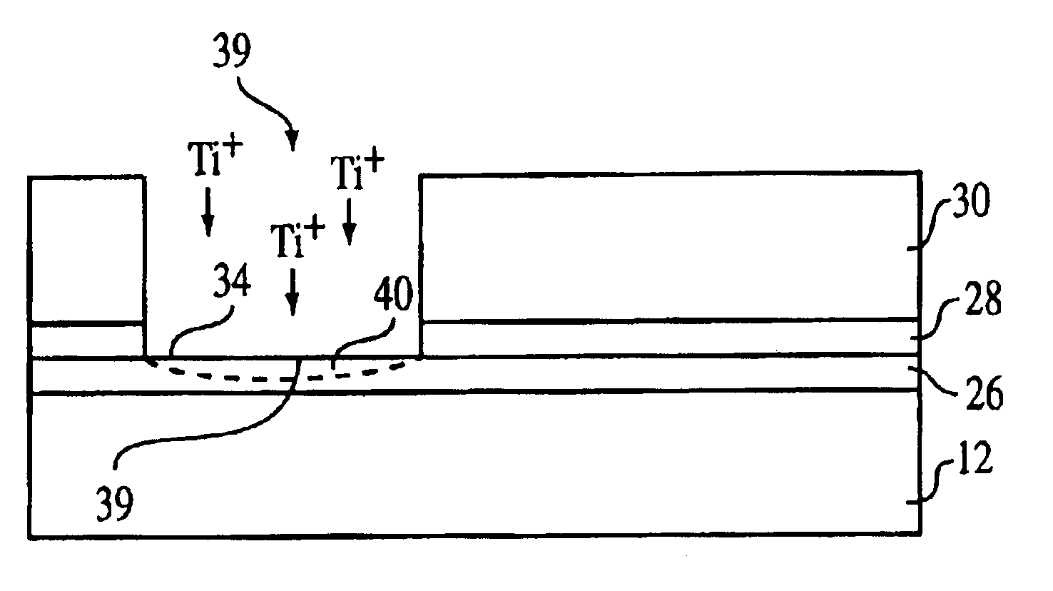
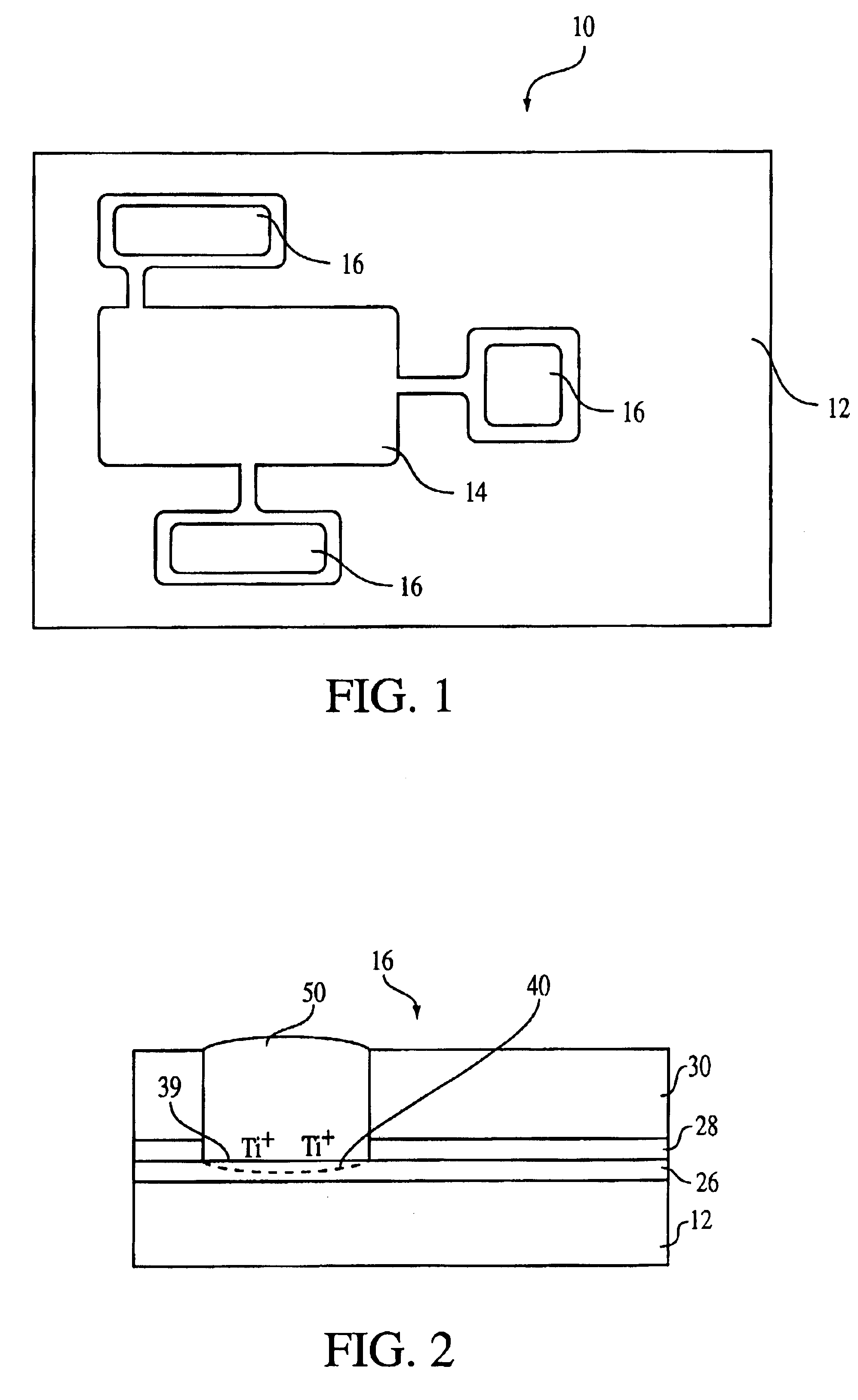
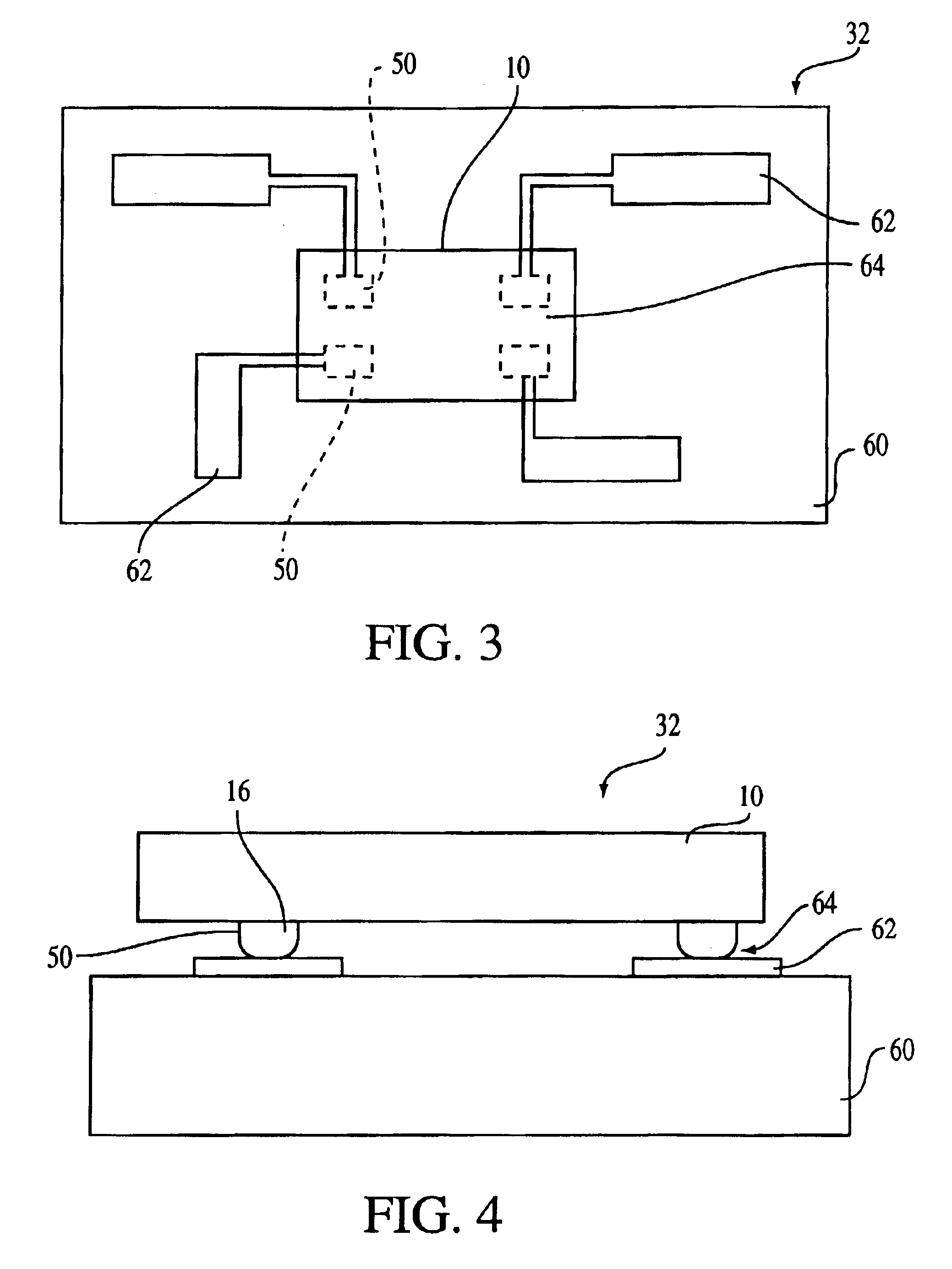
A multi layered copper bond pad for a semiconductor die which inhibits formation of copper oxide is disclosed. A small dose of titanium is implanted in the copper surface. The implanted titanium layer suppresses the copper oxide growth in the copper bond pad by controlling the concentration of vacancies available to the copper ion transport. An interconnect structure such as a wire bond or a solder ball may be attached to the copper-boron layer to connect the semiconductor die to a lead frame or circuit support structure. In another embodiment, a titanium-aluminum passivation layer for copper surfaces is also disclosed. The titanium-aluminum layer is annealed to form a titanium-aluminum-copper alloy. The anneal may be done in a nitrogen environment to form a titanium-aluminum-copper-nitrogen alloy.

Description

FIELD OF THE INVENTIONThe present invention relates to the field of interconnect structures for integrated circuit packages, and in particular, to a copper interconnect structure for electrically connecting two or more electronic components.BACKGROUND OF THE INVENTIONChip interconnection in the semiconductor processing industry often employs two steps. First, in chip bonding, the back of a chip is mechanically attached to an appropriate medium such as a ceramic substrate or a paddle of a metal lead frame. Next, the bond pads on the circuit side of the chip are electrically connected to the package leads by a wire or other electrical conductors to permit utilization of the integrated circuit (IC). Common methods for connecting the bond pads to the leads of lead frame, or the conductors of other conductor support devices, are by wire bonding, Tape Automated Bonding (TAB), Controlled Collapse Chip Connection (C4) or bump bonding, and through the use of conductive adhesives.Aluminum bon...

Claims


Application Information

Patent Timeline
Patent Type & Authority Patents(United States)
IPC IPC(8): H01L23/48H01L23/485H01L23/532H01L23/52H01L21/768
CPCH01L21/76849H01L21/76867H01L24/13H01L21/76886H01L23/53233H01L23/53238H01L24/02H01L24/10H01L2224/13099H01L2924/01005H01L2924/01006H01L2924/01007H01L2924/0101H01L2924/01012H01L2924/01013H01L2924/01014H01L2924/01015H01L2924/01018H01L2924/01022H01L2924/01029H01L2924/01039H01L2924/0104H01L2924/0105H01L2924/01073H01L2924/01074H01L2924/01078H01L2924/01079H01L2924/01082H01L2924/014H01L2924/04941H01L2924/04953H01L2924/05042H01L2924/14H01L2924/01033H01L2924/00H01L24/03H01L24/05H01L2224/0401H01L2224/13H01L2924/15787H01L2924/181
Inventor MCTEER, ALLEN
Owner MICRON TECH INC
Learn More