
Microencapsulated and macroencapsulated drag reducing agents

Inactive Publication Date: 2005-01-11
BAKER HUGHES INC +1
View PDF44 Cites 34 Cited by
  • Summary
  • Abstract
  • Description
  • Claims
  • Application Information

AI Technical Summary

Benefits of technology

Other objects of the invention include providing a DRA that can be readily manufactured and which does not require special equipment for placement in a conduit transporting hydrocarbons or other fluids.
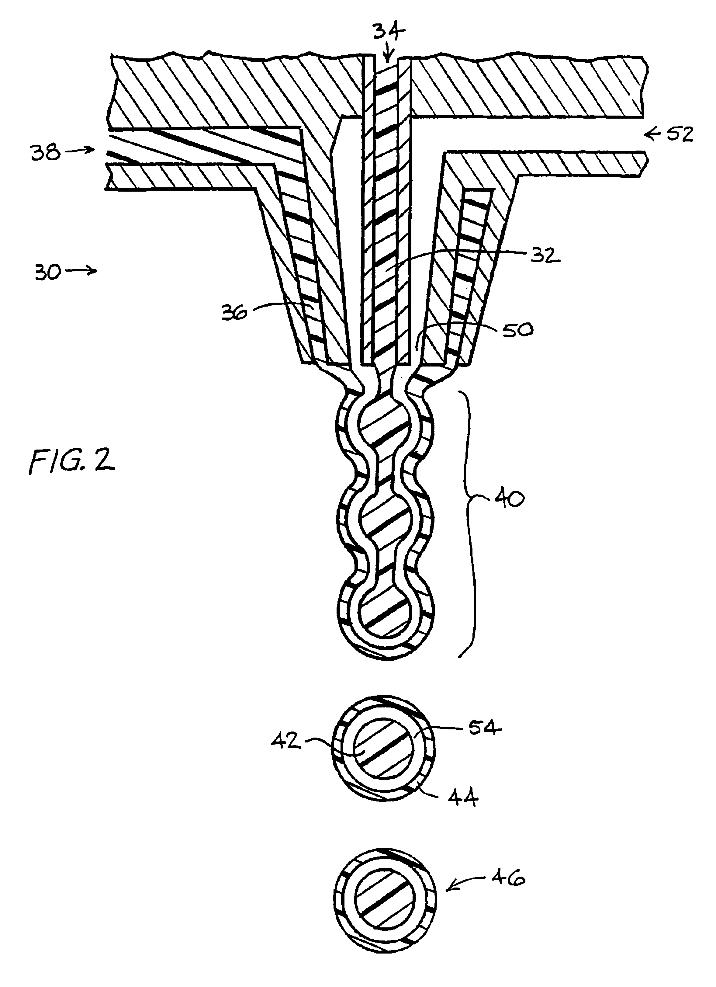
In another embodiment of the invention, prepolymerized DRA could be co-extruded with a polymeric wall or outer cylindrical sleeve or layer that could be pinched by a “pinching and chopping” device. The outer wall or sleeve would be pinched or folded around the cut ends of the DRA to protect the cut ends from cold flowing with other ends with which it comes into contact.
Another embodiment of the invention involves an encapsulated compound for modifying a characteristic of a fluid including a core including polymers formed within the shell and / or monomers which are polymerized within the shell, where the shell is inert to monomer polymerization. The encapsulated compound further includes a shell encapsulating the core, where the shell is at least partially composed of polyethylene oxide of a molecular weight equal to or greater than 100,000 weight average molecular weight, that forms a skin on its outer surface and enables a stable core / shell capsule to form.

Problems solved by technology

A problem generally experienced with simply grinding the poly-alpha-olefins (PAOs) is that the particles will “cold flow” or stick together after the passage of time, thus making it impossible to place the PAO in the hydrocarbon in a form that will dissolve or otherwise mix with the hydrocarbon in an efficient manner.
Further, the grinding process degrades the polymer, thereby reducing the drag reduction efficiency of the polymer.
However, these drag reducing gels also demand specialized injection equipment, as well as pressurized delivery systems.
They are also limited to about 10% polymer as a maximum concentration in a carrier fluid due to the high solution viscosity of these DRAs.
Thus, transportation costs of the DRA are considerable, since up to about 90% of the volume being transported and handled is inert material.

Method used


Image

  • Microencapsulated and macroencapsulated drag reducing agents
  • Microencapsulated and macroencapsulated drag reducing agents

Examples


example 1

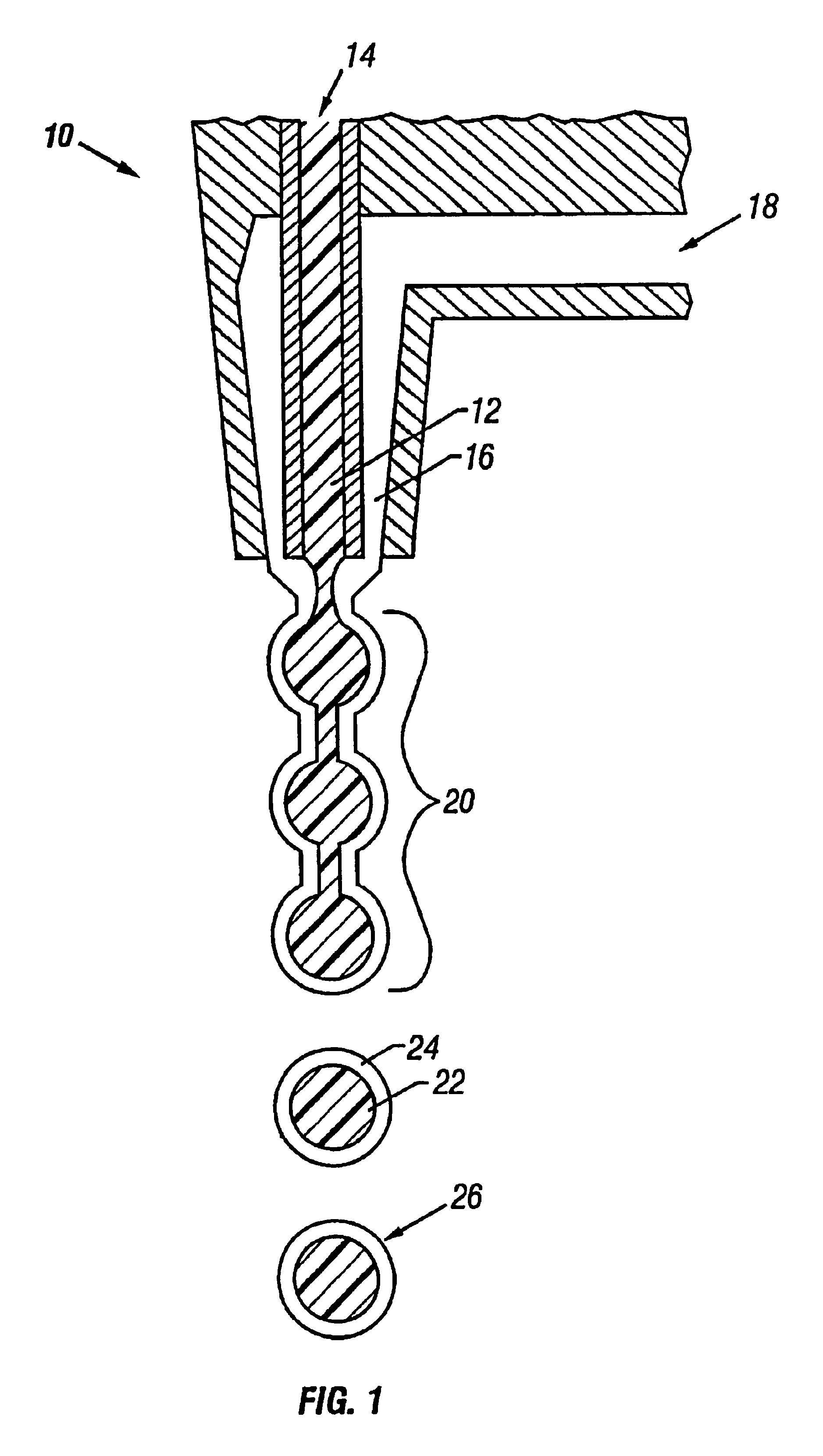
In this Example, a vibrating nozzle technique would be used. The nozzle center bore 12 would have a diameter of 125 μm, where the annulus 16 would have an inner diameter of 130 μm and an outer diameter of 250 μm. The nozzle 10 would vibrate back and forth at a frequency of about 700 Hz to about 1000 Hz.

The core material 14 would be a mixture of alpha-olefins to give a copolymer of polyalpha-olefins as the core 22. A Ziegler-Natta catalyst, in combination with suitable activators, would be added to the core material 14 just prior to its extrusion into the nozzle 10. The Ziegler-Natta catalyst to be used would be TiCl3.AA that is available as a powder from Akzo Chemical Inc., Chicago, Ill. Diethylaluminum chloride (DEAC) and diethylaluminum ethoxide (DEALE) would serve as the preferred activators and are available in the hydrocarbon soluble liquid form from Akzo Chemical. The Ziegler-Natta catalyst would be slurried in a hydrocarbon solvent like kerosene, along with the activators tha...

example 2

This Example would illustrate the microencapsulation of preformed polymer DRA present in a slurry made by a controlled precipitation process. This portion of the Example is similar to that of Example 12 of U.S. Pat. No. 5,733,953, incorporated by reference herein.

The precipitation portion of the inventive process would be carried out in a Ross double planetary mixer. One hundred parts by weight of a 10% solution of FLO 1012 in isopentane would be charged to the mixer. In a separate vessel, 2 parts of magnesium stearate would be slurried in 100 parts of isopropyl alcohol. The magnesium stearate / alcohol slurry would be added in slowly to the copolymer solution with agitation over a two hour period. This procedure would produce a finely divided polyolefin precipitate that would be essentially a dispersion of very fine polymer DRA particles (100 μm to 150 μm) in isopropyl alcohol and isopentane. After precipitation, the concentration of polymer in the slurry would be about 5 wt. %. The ...

example 3

This example would illustrate the microencapsulation of preformed polymer DRA present in a slurry made by a controlled precipitation process. This portion of the example is from Example 12 of U.S. Pat. No. 5,733,953, incorporated by reference herein.

The precipitation portion of the inventive process was carried out in a Ross double planetary mixer. One hundred parts by weight of a 10% solution of FLO 1020 in Isopentane was charged to the mixer. In a separate vessel, 2 parts of magnesium stearate was slurried in 100 parts of isopropyl alcohol. The magnesium stearate / alcohol slurry was added in slowly to the copolymer solution with agitation over a two hour period. This procedure produced a finely divided polyolefin precipitate that is essentially a dispersion of very fine polymer DRA particles (100 μm-150 μm) in isopropyl alcohol and isopentane. After precipitation, the concentration of polymer in the slurry is about 5 wt %. The isopentane which is the polymerization solvent can be r...


PUM

PropertyMeasurementUnit
Lengthaaaaaaaaaa
Electrical resistanceaaaaaaaaaa
Molecular weightaaaaaaaaaa

Abstract

High concentration drag reducing agents may be prepared by microencapsulating and / or macroencapsulating polymer drag reducing agent. The encapsulation may be performed prior to, during, or after the polymerization of monomer into effective drag reducing polymer. If encapsulation is done before or during polymerization, a catalyst may be present, but little or no solvent is required. The result is very small scale bulk polymerization within the capsule. The inert capsule or shell may be removed before, during or after introduction of the encapsulated drag reducer into a flowing liquid. No injection probes or other special equipment is expected to be required to introduce the drag reducing slurry into the liquid stream, nor is grinding (cryogenic or otherwise) of the polymer necessary to form a suitable drag reducing agent.

Description

FIELD OF THE INVENTIONThe invention relates to encapsulating compounds to be added to fluids to modify a characteristic thereof, more particularly to agents to be added to fluids flowing through a conduit to reduce the drag therethrough, and most particularly to encapsulated drag reducing agents (EDRAs) for liquids such as hydrocarbons, aqueous solutions, and emulsions of water and hydrocarbons. The drag reducing agents are encapsulated in a shell that is removed prior to, during and / or after introduction of the EDRA into the flowing fluid.BACKGROUND OF THE INVENTIONThe use of polyalpha-olefins or copolymers thereof to reduce the drag of a hydrocarbon flowing through a conduit, and hence the energy requirements for such fluid hydrocarbon transportation, is well known. These drag reducing agents or DRAs have taken various forms in the past, including slurries of ground polymers to form particulates. A problem generally experienced with simply grinding the poly-alpha-olefins (PAOs) is...

Claims


Application Information

Patent Timeline
IPC IPC(8): B01J13/04B01J13/22B01J13/20F17D1/17F17D1/00C10L1/14C10L1/16C10L1/18
CPCB01J13/04B01J13/22C10L1/143C10L1/146F17D1/17B01J13/206Y10T428/2987C10L1/1641C10L1/1691C10L1/1881C10L1/1963C10L1/198C10L1/1985Y10T428/2989Y10T428/2985Y10T428/2984Y10T137/0335
Inventor KOMMAREDDI, NAGESH S.DINIUS, RYANVASISHTHA, NIRAJBARLOW, DARREN EUGENE
Owner BAKER HUGHES INC
Learn More