High-speed wavelength channel selector and high-speed photonic integrated circuit-type space and wavelength multiplexed channel selector employing the same

Inactive Publication Date: 2005-01-18
ELECTRONICS & TELECOMM RES INST
View PDF9 Cites 3 Cited by
  • Summary
  • Abstract
  • Description
  • Claims
  • Application Information

AI Technical Summary

Benefits of technology

It is, therefore, a primary object of the present invention to provide a wavelength channel selector having properties of relatively easy manufacturing and easy extension to multi-channel integration by solving the problems related to the conventional schemes. The present invention reduces shortcomings of the conventional

Problems solved by technology

However, there has been no report on hybrid or monolithic integrated high-speed wavelength channel selectors using electro-optic switches made of non-crystalline materials, such as electro-optic polymer or glass materials, with the wavelength multiplexer(s) and demultiplexer(s).
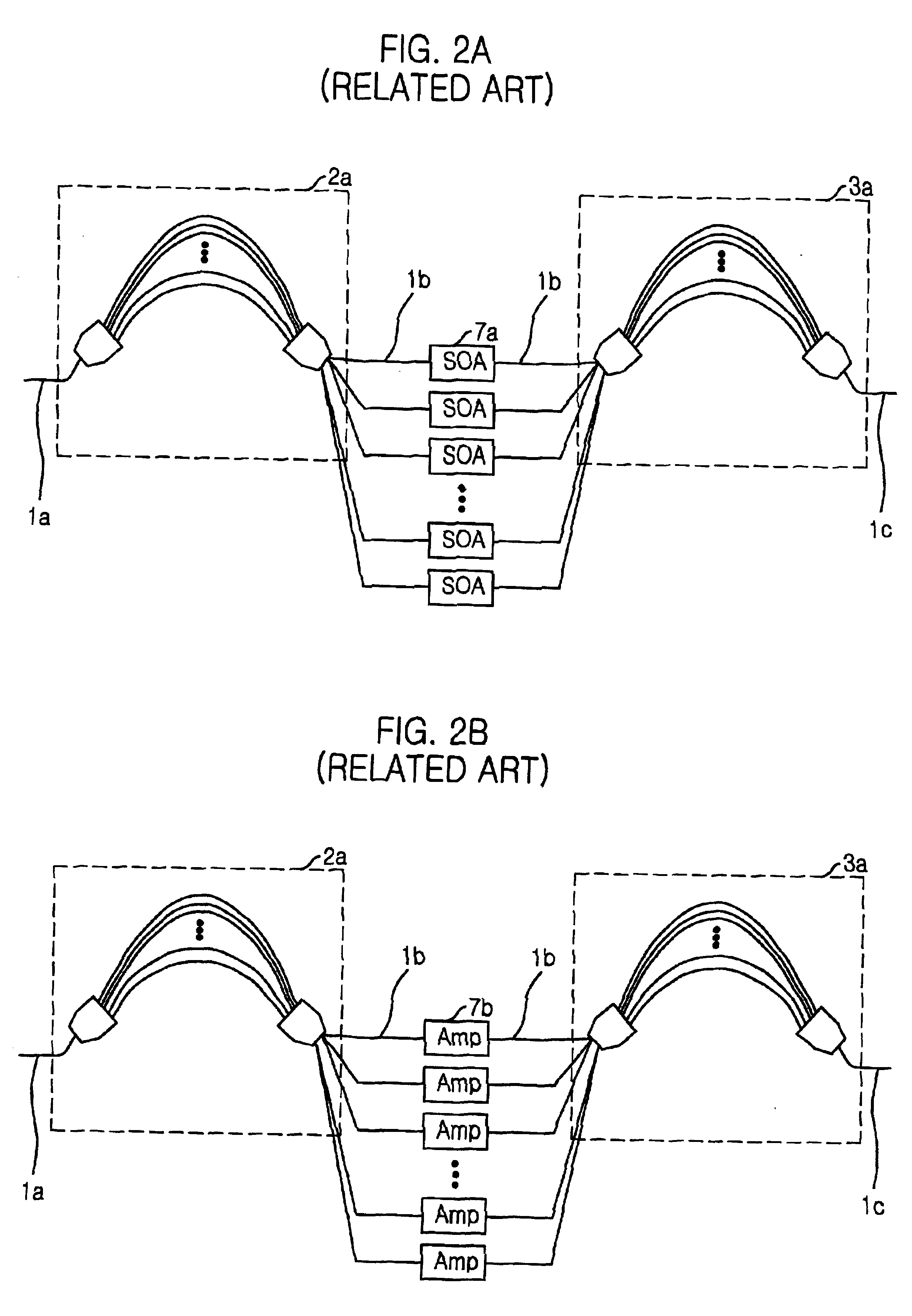
The SOAGs 7a have advantages of small volume and optical gain, but have technical limitations on achieving a high yield on device fabrication due to complicate and high cost device fabrication processes.
Furthermore, current technologies use either hybrid integration of the SOAGs with the silica arrayed waveguide gratings, which require cost and time consuming device integration processes, or monolithic integration of the SOAGs with semiconductor arrayed waveguide gratings, which have poor waveguide characteristics and difficulties in device fabrication yet.
When using electro-optic switches such as LiNbO3 switches in this scheme, monolithic integration with a wavelength multiplexer and a wavelength demultiplexer is not easily realizable, but only hybrid integration is required.
The hybrid integration has a disadvantage of difficult device fabrication.
This scheme employing the wavelength tunable filters 7d and the wavelength converters 5 has difficulties on high-speed channel selection and channel locking of the tunable filters, and has a problem in practical system applications due to a complicate geometry caused by using many wavelength converters.
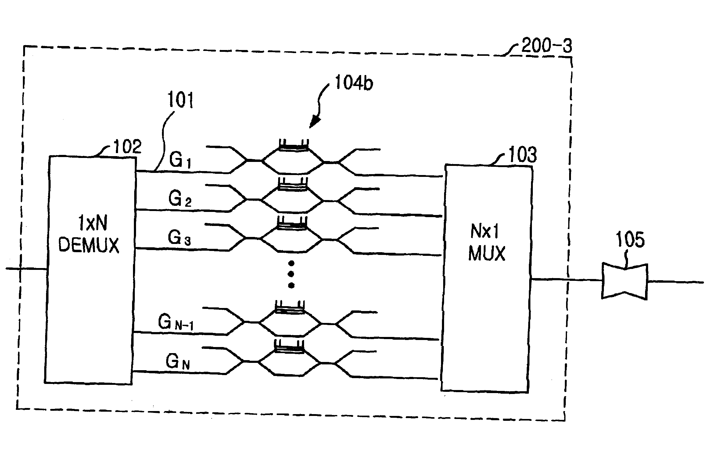
This scheme is not good for high-speed switching because it requires many cascaded switch operations between input and output paths and a complicate control process to operate the sw

Method used


Image

  • High-speed wavelength channel selector and high-speed photonic integrated circuit-type space and wavelength multiplexed channel selector employing the same
  • High-speed wavelength channel selector and high-speed photonic integrated circuit-type space and wavelength multiplexed channel selector employing the same
  • High-speed wavelength channel selector and high-speed photonic integrated circuit-type space and wavelength multiplexed channel selector employing the same

Examples


Example

Hereinafter, with reference to the accompanying drawings, some preferred embodiments of the present invention will be explained in detail. It should be noticed that, when assigning reference numerals to components illustrated in each drawing, components performing a same or similar function are represented by same or similar reference numerals although they are shown in different drawings.

Referring to FIG. 10, there is shown a block diagram of a high-speed wavelength channel selector B in accordance with the present invention, which is based on a singly integrated scheme of a pair of wavelength demultiplexer 102 and multiplexer 103, a planar waveguide-type electro-optic switch array 104 of electro-optic non-crystalline materials, such as electro-optic polymers or glasses, placed between the demultiplexer 102 and the multiplexer 103, and input and output optical waveguides 101a and 10b located at signal input and output ports, respectively.

The high-speed wavelength channel selector B...


PUM


Abstract

A high-speed wavelength channel selector has properties of relatively easy manufacturing and easy extension to multi-channel integration, and a high-speed space and wavelength multiplexed channel selector uses the high-speed wavelength channel selector. The high-speed wavelength channel selector is integrated with electro-optic waveguide switches of non-crystalline materials, such as electro-optic polymers or glasses, in the middle of a pair of wavelength multiplexer and demultiplexer and the high-speed space and wavelength multiplexed channel selector has the photonic integrated circuit-type composition of a space multiplexed channel selector containing M electro-optic waveguide switches and an M×1 channel combiner, the high-speed wavelength channel selector, optical amplifier and a high-speed wavelength converter.

Description

FIELD OF THE INVENTIONThe present invention relates to a high-speed planar waveguide-type optical wavelength channel selector based on electro-optic switches using electro-optic non-crystalline materials such as electro-optic polymer and glass materials, and further to its applications for high-speed photonic integrated space- and wavelength-division channel selecting switch fabrics intended for optical communication network node systems.BACKGROUND OF THE INVENTIONHigh-speed wavelength channel selectors have been demonstrated in various schemes by positioning optical switches, such as semiconductor optical amplifier gates, optical amplifiers, electro-optic single crystal switches, or tunable optical filters, between a pair of arrayed waveguide gratings for optical packet signal processing systems.The conventional schemes use combinations of the optical switches of semiconductor optical amplifier gates or electro-optic single crystal switches with silica or semiconductor wavelength m...

Claims


Application Information

Patent Timeline
IPC IPC(8): H04J14/02H04Q11/00G02B6/35G02B6/34G02B6/293
CPCH04J14/02H04Q11/0005G02B6/12004G02B6/12007H04J14/0221H04Q2011/0011G02B6/356H04Q2011/0024G02B6/12021H04Q2011/0016G02B6/293
Inventor KIM, KYONG HONAHN, JOON TAECHOI, YONG GYUCHO, DOO-HEE
Owner ELECTRONICS & TELECOMM RES INST
Why Eureka
Try Eureka