
Internal combustion engine with injection of gaseous fuel

a gaseous fuel and internal combustion engine technology, applied in the direction of combustion process, fuel supply apparatus, combustion ignition, etc., can solve the problems of increasing the fuel consumption of over 40%, gaseous fuels typically do not ignite as readily, and the fuel consumption of liquid-fueled engines is not suitable, so as to reduce nitrogen oxide emissions and high ignition reliability

Inactive Publication Date: 2005-01-25
WESTPORT POWER
View PDF17 Cites 9 Cited by
  • Summary
  • Abstract
  • Description
  • Claims
  • Application Information

AI Technical Summary

Benefits of technology

A method and apparatus is provided for injecting gaseous fuel into the combustion chamber of an unthrottled high compression engine. For example, in an engine with a compression ratio of between 16:1 and 18:1, the gaseous fuel can be injected at a high pressure of approximately 200 bar, towards the end of the compression stroke. This results in the formation of an inhomogeneous fuel-air mixture, similar to that found in a diesel engine. A high-speed gaseous fuel injection valve is employed to inject the gaseous fuel into the combustion chamber. The combustion chamber is defined by a cylinder, a piston that is reciprocable within the cylinder, and a cylinder head covering one end of the cylinder. The combustion chamber can be further defined in part by a piston bowl or recess formed in the piston head (which is the end surface of the piston that faces the combustion chamber). Using the present method and operating with a compression ratio substantially the same as that of an equivalent diesel engine, it is possible to reduce the modifications required for natural gas operation and to reduce manufacturing costs, by shaping the combustion chamber so that it corresponds largely to the geometry of combustion chambers found in conventional diesel engines.
On account of the high ignition reliability of the fuel-air mixture that is achievable with the disclosed ignition device, the engine's exhaust gas is particularly suitable for re-circulating a controlled amount back into the engine's air intake system, using what are known as techniques for exhaust gas recirculation (“EGR”). Accordingly, in a preferred embodiment the engine further comprises an EGR system for directing into an air intake system, a portion of the exhaust gas exhausted from the combustion chamber. The recirculated exhaust gas can be cooled or uncooled before being introduced into the air intake system, depending upon the engine's operating conditions. With the disclosed method, exhaust gas recirculation rates of up to 70% can be employed to reduce nitrogen oxide emissions.

Problems solved by technology

However, a problem with replacing liquid fuel with such gaseous fuels in a conventional internal combustion engine has been that such gaseous fuels typically do not ignite as readily as liquid fuels.
In addition, the fuel supply system and the manner of introducing the fuel into the engine typically require equipment specialized for handling gaseous fuels.
Accordingly, a design suitable for a liquid-fueled engine may not be suitable for a gaseous-fueled engine without considerable modifications, which can influence commercial viability.
When operating frequently under low load, as is typical for buses operating in cities, the throttle control has been found to be responsible for an increase in fuel consumption of above 40%.
However, lean-mix engines still may suffer from significant power disadvantages in comparison to the power levels achieved by Euro 3 type liquid-fueled diesel cycle engines.
Since the ability to operate today's lean-mix engines on even leaner mixes is limited, especially in the lower partial load range, to λ values of 1.2 to 1.4, due to the slow rate of combustion of natural gas, these engines also require throttle control.
For example, during everyday operation of a city bus, this results in fuel consumption values that are up to 30% higher because of the large proportion of operating time when the engine operates under idle or low load conditions.
However, conventional glow plugs like those used in diesel engines are designed to provide ignition assistance only during start-up because diesel fuel readily auto-ignites at the pressures and temperatures normally present in a diesel engine once it is running.
Continuous activation of a conventional glow plug, which is only designed for brief use during start up, can lead to early failure.
Experiments have shown that the length of a glow plug's service life generally decreases as operating temperature increases, and that conventional glow plugs can not be relied upon to provide the durability that operators of gaseous-fueled internal combustion engines are expected to demand.
The '081 patent further discloses coating the interior and exterior of the shield with a ceramic refractory material, such as a metal oxide that acts as a thermal barrier so that the shield reduces the cooling effect of the inlet gas on the glow plug and also reduces the electrical power needed by the glow plug to maintain a surface temperature suitable for sustaining good combustion.

Method used


Image

  • Internal combustion engine with injection of gaseous fuel
  • Internal combustion engine with injection of gaseous fuel
  • Internal combustion engine with injection of gaseous fuel

Examples


Embodiment Construction

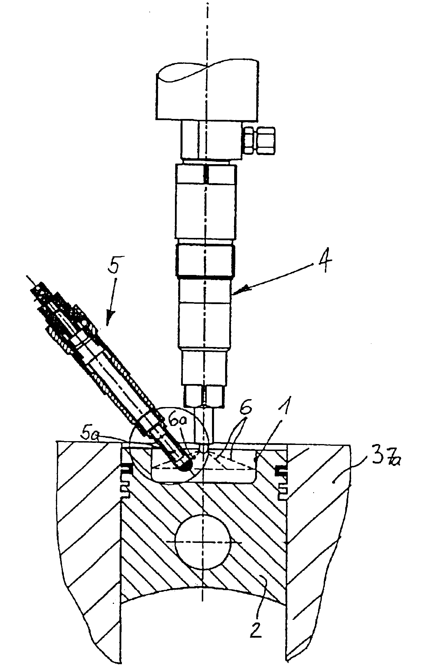
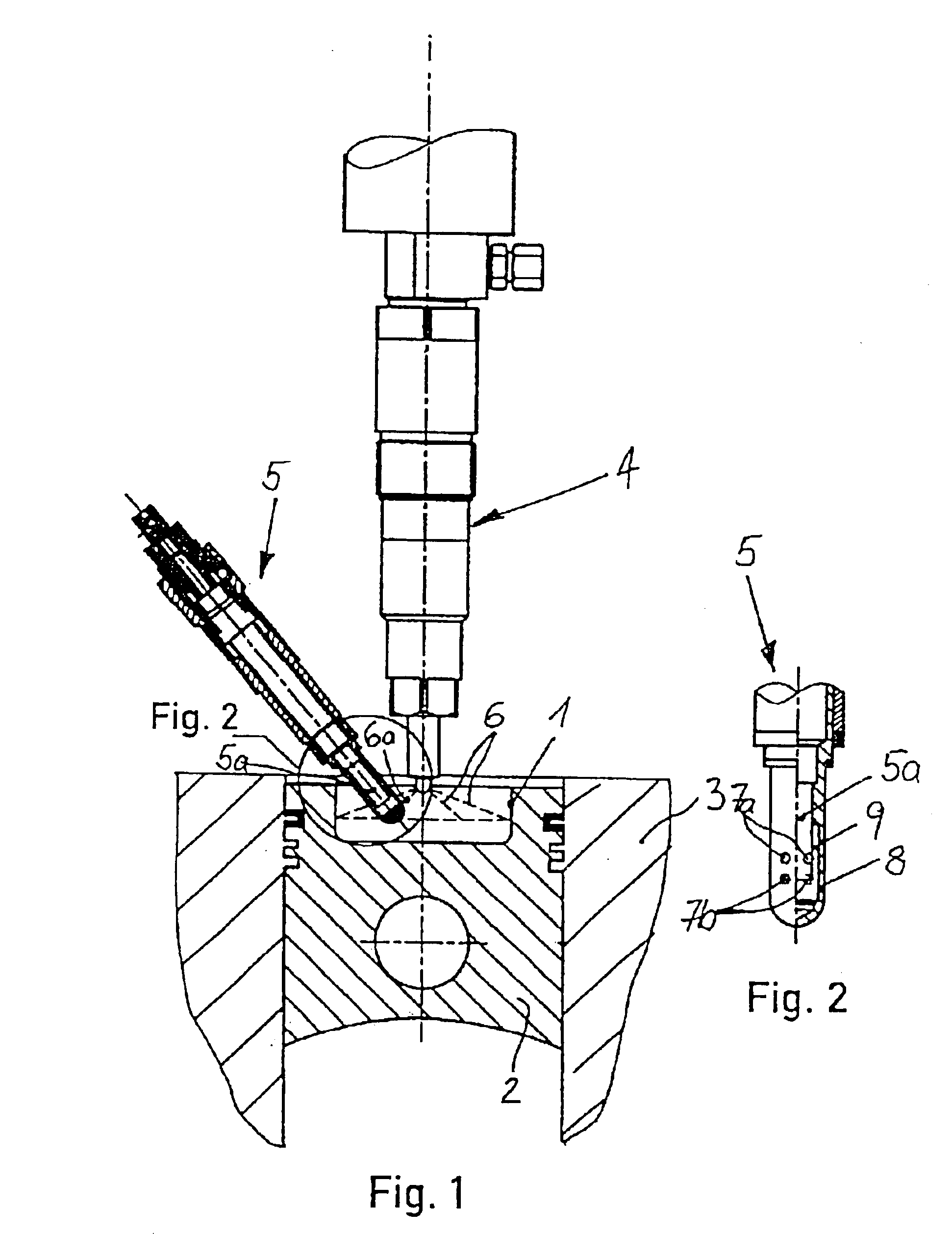
FIG. 1 is a partial cross-section of a gaseous-fueled internal combustion engine illustrating a preferred embodiment of a combustion chamber, which is defined by cylinder 10, piston 12, which is reciprocable within cylinder 10, and cylinder head 14, which covers the top end of cylinder 10. Fuel injection valve 20 and ignition device 30 are mounted in cylinder head 14 with respective tips that extend into the combustion chamber. This internal combustion engine can be of an inline- or V-design with any desired number of cylinders and displacement.

Piston 12 preferably is substantially the same as the piston employed in an equivalent diesel-fueled engine, and typically comprises chamber recess 13. A simple shape for chamber recess 13 is shown for illustrative purposes, but persons skilled in the technology will understand that other shapes can be employed. For example, smaller engines can use a re-entrant combustion chamber with a pip to promote turbulence for improved mixing. The rapid...


PUM


Abstract

An internal combustion engine comprises a fuel injection nozzle for injecting a gaseous fuel directly into the combustion chamber. Installed in close proximity to the fuel injection nozzle is an ignition device, comprising a sleeve that provides a shielded space around a hot surface igniter. The sleeve restricts flow between the shielded space and the combustion chamber. An inlet opening in the sleeve allows air and fuel to enter the shielded space to form a combustible mixture therein. The sleeve contains a substantial amount of the combustible mixture within the shielded space until it ignites and pressure builds within the shielded space to propel a combustion flame through at least one discharge opening that is oriented to direct the combustion flame into contact with the fuel spray roots emerging from the fuel injection nozzle.

Description

TECHNICAL FIELDThe invention relates to an apparatus and method for operating a gaseous-fueled internal combustion engine that comprises a fuel injection nozzle with a nozzle disposed in a combustion chamber for injecting gaseous fuel directly into the combustion chamber. An ignition device, also disposed within the combustion chamber, is installed in close proximity to the fuel injection nozzle. The ignition device comprises a sleeve that provides a shielded space around a hot surface igniter. The sleeve restricts flow between the shielded space and the combustion chamber to prevent excessive cooling of the igniter between combustion events while allowing a combustible mixture to form within the shielded space until it ignites. The sleeve also allows pressure to build within the shielded space to a level sufficient to propel a combustion flame into the combustion chamber to ignite the charge therein.BACKGROUNDLiquid-fueled internal combustion engines have been used to produce power...

Claims


Application Information

Patent Timeline
Patent Type & Authority Patents(United States)
IPC IPC(8): F02B23/06F02B23/02F02B43/00F02F3/26F02M21/02F02B23/10F02B3/06F02B3/00F02B75/12F02B75/00
CPCF02B23/0639F02B23/0657F02B43/00F02M21/0275F02F3/26F02M21/0245F02B3/06F02B23/0669F02B23/101F02B2275/14Y02T10/125Y02T10/123Y02T10/32F02B2075/125F02M21/0269Y02T10/12Y02T10/30
Inventor HILGER, ULRICHBARTUNEK, BERND
Owner WESTPORT POWER
Learn More