

Photovoltaic cell
a photovoltaic cell and photovoltaic transducer technology, applied in the field of photovoltaic cells, can solve the problems of poor long-term stability, deterioration poor performance of photovoltaic transduction efficiency, so as to improve the apparent curve factor (ff) and configuration factor, reduce the energy loss of electrons moving through the electrolyte layer, and improve the effect of optical and electrical characteristics
- Summary
- Abstract
- Description
- Claims
- Application Information
AI Technical Summary
Benefits of technology
Problems solved by technology
Method used
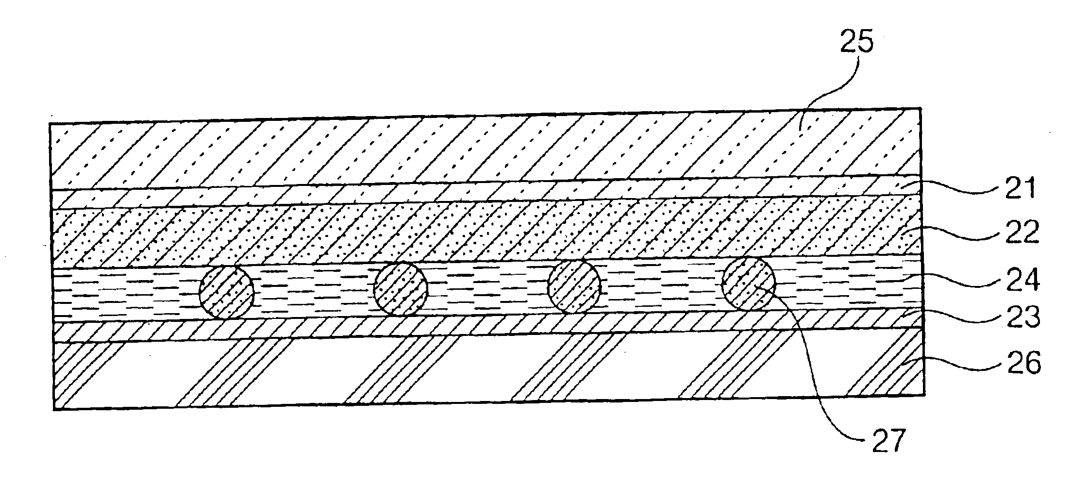
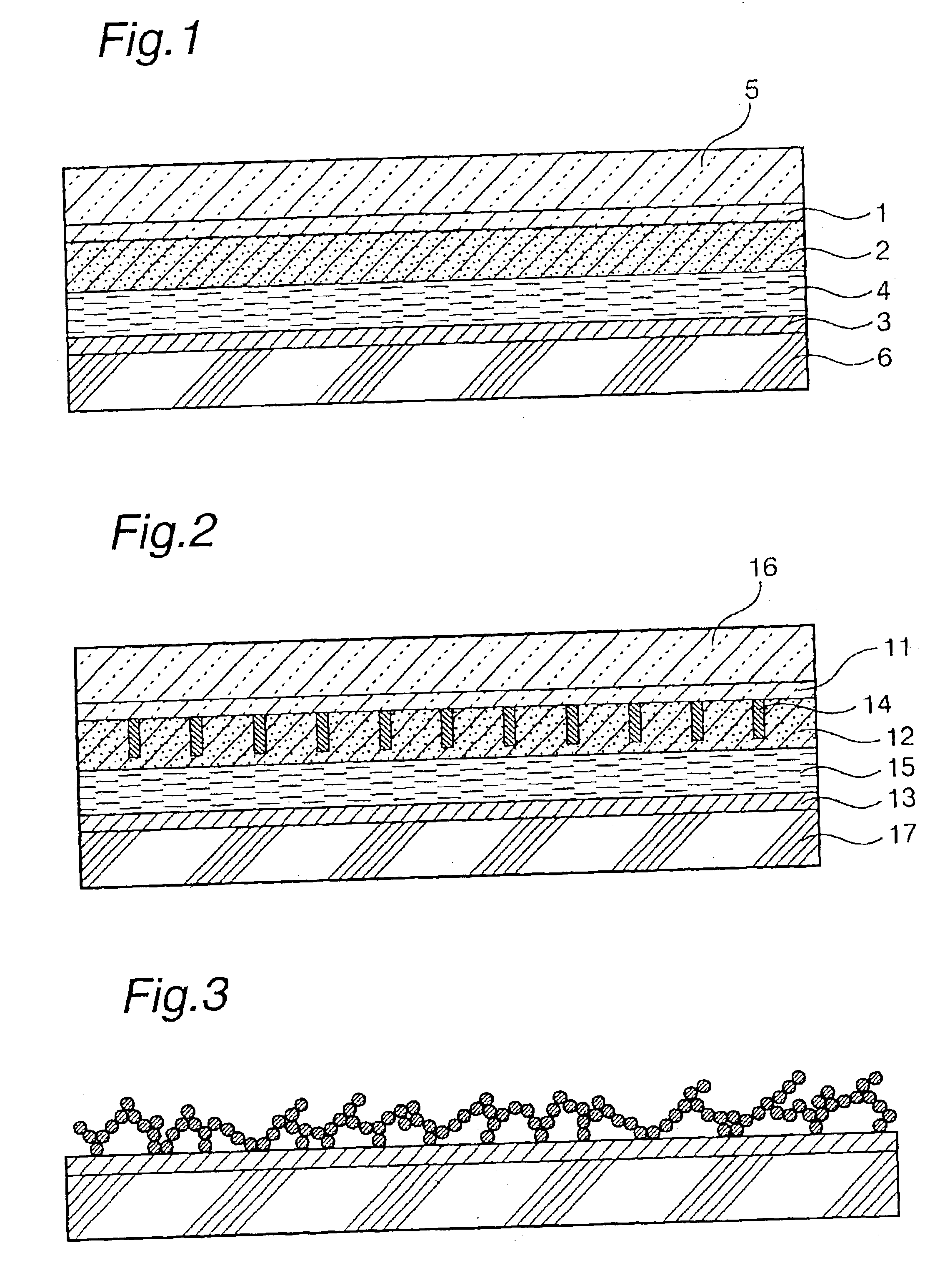
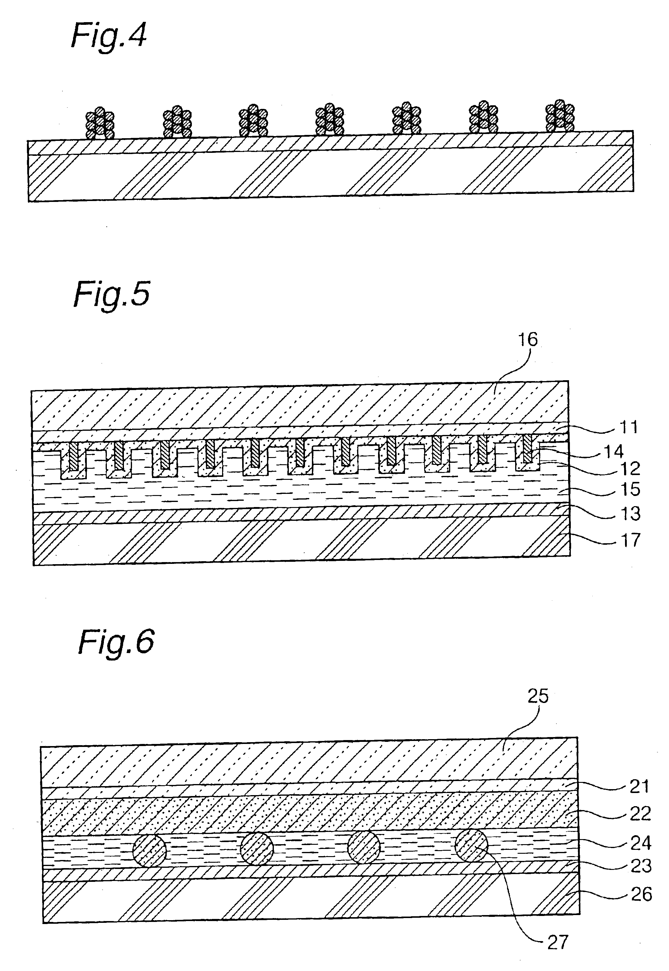
Image

Examples
example 1
5 g of titanium hydride was suspended in 1 lit. of pure water, 400 g of an aqueous hydrogen peroxide solution of 5% by weight concentration was added to the suspension over a period of 30 min, and heated to 80° C. to effect dissolution. Thus, a solution of peroxotitanic acid was obtained. 90% by volume was divided from the whole amount of the solution, and its pH was adjusted to 9 by adding concentrated aqueous ammonia. The resultant mixture was placed in an autoclave and subjected to a hydrothermal treatment at 250° C. for 5 hr under saturated vapor pressure. Thus, titania colloid particles were obtained. The obtained titania colloid particles were analyzed by X-ray diffractometry, and it was found that they consisted of highly crystalline anatase titanium oxide. The average crystallite diameter and average particle diameter of particulate anatase titanium oxide are listed in Table 1.
Subsequently, the obtained titania colloid particles were concentrated to a concentration of 10% an...
example 2
Preparation of Photovoltaic Cell
Acetonitrile and ethylene carbonate were mixed together at a volume ratio (acetonitrile:ethylene carbonate) of 1:4 to thereby obtain a solvent. This solvent was mixed with the same liquid crystal as in Example 1 at a ratio of 30% by volume: 70% by volume. Tetrapropylammonium iodide and iodine were mixed thereinto in respective concentrations of 0.46 and 0.06 mol / lit. Thus, a mixture for electrolyte layer consisting of a liquid crystal and an electrolyte was obtained.
A photovoltaic cell was prepared in the same manner as in Example 1, except that the above mixture for electrolyte layer was interposed between the electrodes. With respect to the photovoltaic cell, the Voc, Joc, FF, η and long-term stability were evaluated. The results are given in Table 1.
example 3
18.3 g of titanium tetrachloride was diluted with pure water, thereby obtaining an aqueous solution of 1.0% by weight concentration in terms of TiO2. Aqueous ammonia of 15% by weight concentration was added to the aqueous solution under agitation, thereby obtaining a white slurry of pH 9.5. This slurry was filtered and washed, thereby obtaining a cake of titanium oxide hydrate gel of 10.2% by weight in terms of TiO2. This cake was mixed with 400 g of a 5% aqueous solution of hydrogen peroxide, and heated to 80° C. to thereby effect dissolution. Thus, a solution of peroxotitanic acid was obtained.
90% by volume was divided from the whole amount of the solution, and its pH was adjusted to 9 by adding concentrated aqueous ammonia. The resultant mixture was placed in an autoclave and subjected to a hydrothermal treatment at 250° C. for 5 hr under saturated vapor pressure. Thus, titania colloid particles were obtained. The obtained titania colloid particles were analyzed by X-ray diffract...
PUM
| Property | Measurement | Unit |
|---|---|---|
| roughness | aaaaa | aaaaa |
| diameter | aaaaa | aaaaa |
| surface roughness | aaaaa | aaaaa |
Abstract
Description
Claims
Application Information