High contrast surface marking using mixed organic pigments

a technology of organic pigments and high contrast, applied in the field of high contrast surface marking using organic pigments, can solve the problems of inability to mark transparent enameled objects, material damage, and inability to meet the requirements of the product,

Inactive Publication Date: 2005-02-15
THERMAX LLC
View PDF78 Cites 26 Cited by
  • Summary
  • Abstract
  • Description
  • Claims
  • Application Information

AI Technical Summary

Benefits of technology

The main aspect of the present invention is to provide a method to quickly, with high-resolution, high-contrast, and permanence, mark the surface of a workpiece.
Prior to the present invention, no quick and permanent method existed for marking certain substrate materials with enhanced contrast and / or color which would also permit the rapid change of content and / or information in the mark without structural damage to the substrate material. In theory, an optical power source, properly focused, could create the same temperatures obtained by ovens and / or kilns used in conventional “firing” processes involving marking materials. The speed of computer controls for the optical power source, the beam steering mechanism and the mark content make it possible for individual enhanced contrast and / or color marks to be bonded to the various substrate materials in extremely short time periods without structural damage in a way not attainable by any other marking or decorating process. The wide variety of marking materials make it possible to produce images with varying optical properties including, but not limited to, contrast, color, reflectance, diffraction; and varying physical properties including, but not limited to, thickness, durability, stability, structural shape and electrical conductivity.
The present inventive process of permanently marking materials will be especially useful in marking glass, ceramic, porcelain, and other brittle materials whose surface structure cannot withstand the thermal shock of other commonly used high-power pulsed laser marking methods. In the present invention, the resulting image on all substrate materials has enhanced contrast and / or color which makes the mark more easily viewed and imaged by the human eye and / or machine vision equipment and is highly resistant to chemical and mechanical wear. This feature is a great advance in barcode and 2D symbology marking, whereas the prior art high-power pulsed laser-only marking systems cannot always create sufficient contrast and / or color markings.
CO2 lasers are capable of permanently marking glass materials by thermally shocking the surface and causing fractured facets. These fractures are detrimental to the structural integrity of the glass and will continue to propagate, causing chips to fall out of the mark. Furthermore, the imaged mark has no enhanced contrast and is difficult to view or image. Certain organic materials (wood, plastic, etc.) are easily marked using CO2 lasers, but the resulting imaged mark can only have limited color and / or contrast based on the material composition and the effect of the laser energy (it will cause burning of the surface). There are a number of specially formulated plastic materials that will change color when exposed to specific laser energy and produce an enhanced contrast mark.
The principal advantages of the inventive process are:no structural damage to the substrate material surface;no post processing required to stabilize the finished mark;wide variety of colors, contrasts and physical properties;high resolution for the imaged mark;resistant to chemical and mechanical wear;marking speeds in seconds not minutes or hours;image content can be changed at computer speeds; andindividual marks can be fully automated.
Features of the inventive process believed to be new are:1) The use of laser or diode based radiation to rapidly elevate the temperature of the marking material atop the substrate to form a new marking layer atop the substrate.2) a single laser beam pass is all that is required.3) Selecting marking materials specially formulated to react with specific substrate materials using laser or diode based radiation as the catalyst.4) Speed with which the mark can be produced.5) Speed with which the content of the mark can be changed.6) Method of delivery of marking material to the substrate surface.7) Marks can be applied to glass and other brittle surfaces without fracturing.8) Enhanced contrast and / or color of mark.9) Two-, three-, or four-color images can be marked with near photo quality.10) Elimination of any firing step of entire workpiece.11) Ability to first ablate (if desired) and then mark selected substrates to create 3D high-contrast markings with a simple two-step process.12) Using relatively low-cost, low-contaminating marking materials (glass frits, mixed metal oxides, or mixed organic pigments) instead of silver oxides or other high-cost highly-toxic materials.13) Higher resolution of imaged mark (>1000 dpi).

Problems solved by technology

In these methods, the surface of the marked material is altered with the consequence that the material may suffer damage, especially if marking is effected by etching, engraving, or cutting.
The markings so produced are not always satisfactory in all respects.
A drawback of this method is that, for example, transparent enameled objects cannot be marked because the opacifying agent incorporated in the enamel coating does not change optically at the non-irradiated areas and, therefore, strongly influences the overall appearance of the object.
Furthermore, the opacifying agent employed may adversely affect the mechanical properties of the enamel.
The problem with these processes is the time factor and energy consumption are not commercially efficient to create the indicia.
Furthermore, these processes do not lend themselves to portability.
This method cannot be used on glass, ceramic, or other brittle materials because of surface damage and / or breakage.
There is a UV cure step which is time consuming.
The problem with this and all ink methods is a lack of permanence.
Even with these hazardous solvents however, significant improvement has not been achieved.
The problem with this method is the burden of creating a time consuming glaze surface before applying the high-speed laser beam.
The problem with this method is the time and energy-consuming step of firing and cooling the workpiece.

Method used


Image

  • High contrast surface marking using mixed organic pigments
  • High contrast surface marking using mixed organic pigments
  • High contrast surface marking using mixed organic pigments

Examples


Embodiment Construction

AND FIGURES

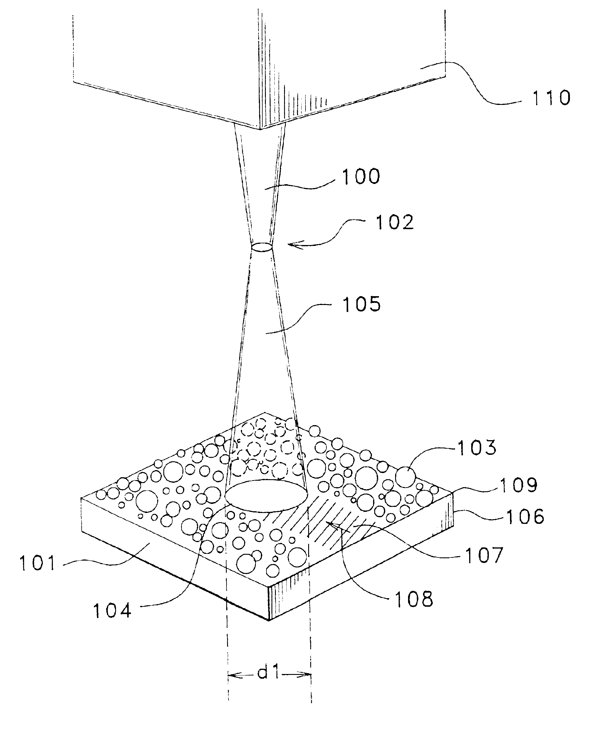
In all the below listed figures, the resulting marks were produced on commercially available Nd:YAG laser markers as manufactured, for example, by Lumonics Corporation, A B Lasers, Inc., Controlaser, Inc., and / or Rofin Sinar, Inc. with power capability and optical configurations capable of providing the referenced marker parameters. In all examples the laser marker utilized produced a spot size of 100 to 125 microns, and the surface of the workpiece was placed 2 mm to 3 mm below the focal plane of the laser beam. In FIG. 2 through FIG. 8 the marking material was manually applied using a soft brush with resulting thicknesses varying between 75 and 125 microns on the workpiece surface.

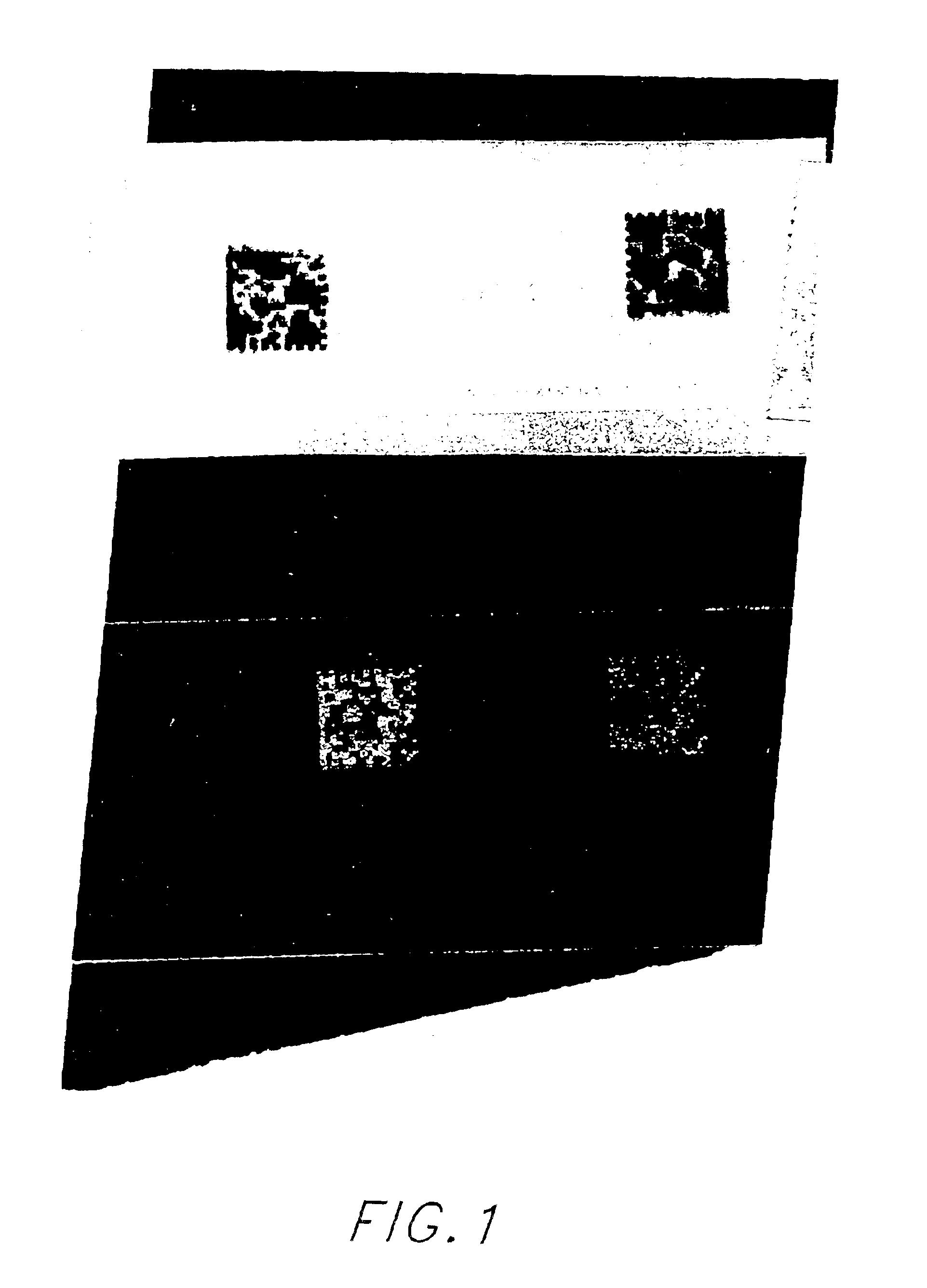
FIG. 1 is a photograph of a transfer label using Cerdec 24-2702 glass frit containing energy absorbing enhancers as the marking material having a thickness of approximately 250 microns and a soda-lime glass microscope slide workpiece after the inventive process. The left mark was produced usin...


PUM

PropertyMeasurementUnit
thicknessaaaaaaaaaa
thicknessaaaaaaaaaa
wavelengthaaaaaaaaaa

Abstract

A method of laser marking metals, plastics, ceramic materials, glazes, glass ceramics, and glasses of any desired form, which includes applying to the material to be marked a variable thickness layer of marking material containing energy absorbing enhancers then irradiating said layer with a laser or diode based energy source such that the radiation is directed onto said layer in accordance with the form of the marking to be applied, and using a laser or diode based energy source of a wavelength which is sufficiently absorbed by the marking material so as to create a bonding of the marking material to the surface of the workpiece at the irradiated areas.

Description

FIELD OF INVENTIONThe present invention relates to a method of producing permanent, enhanced contrast and / or color markings formed as a new marking layer on top of substrates including glass, ceramic, porcelain, metal, and plastic. A laser beam irradiates a marking medium having a glass frit containing an energy absorbing enhancer, or alternatively the marking medium can be a mixed metal oxide or a mixed organic pigment.BACKGROUND OF THE INVENTIONThe marking of ceramic materials, glazes and glasses can be effected by conventional marking and decoration methods such as etching, cutting, engraving, grinding or by applying a glass or glaze colorant. In these methods, the surface of the marked material is altered with the consequence that the material may suffer damage, especially if marking is effected by etching, engraving, or cutting. The application of a glass or glaze colorant necessitates, in addition, a second firing step. The markings so produced are not always satisfactory in a...

Claims


Application Information

Patent Timeline
Patent Type & Authority Patents(United States)
IPC IPC(8): B41M5/26G06K1/12G06K1/00C03C23/00
CPCB41M5/262G06K1/126B41M5/267C03C23/0025B41M5/26
Inventor HARRISON, PAUL WOLLCOTT
Owner THERMAX LLC
Why Eureka
Try Eureka