Micromechanical resonator device and micromechanical device utilizing same

a micromechanical and resonator technology, applied in relays, generators/motors, snap-action arrangements, etc., can solve the problems of consuming a sizable portion of the total sub-system area, devices posing an important bottleneck against the ultimate miniaturization and portability of wireless transceivers, and reducing power handling capacity, so as to improve power handling capacity, improve q, and improve the effect of siz

Inactive Publication Date: 2005-02-15
RGT UNIV OF MICHIGAN
View PDF17 Cites 105 Cited by
  • Summary
  • Abstract
  • Description
  • Claims
  • Application Information

AI Technical Summary

Benefits of technology

The micromechanical disk resonators presented here have the potential to extend the frequency of micromechanical devices well into the GHz range, making them viable in all stages of wireless systems (including cellular phones) from the RF front-end down to IF filtering and mixing and enabling a completely integrated, single chip transceiver.
Disk resonators of the present invention have advantages over the freely supported and clamped—clamped beams used in previous HF designs, including the capability to reach UHF frequencies using low numbered mode shapes, typically leading to improved Q....

Problems solved by technology

At present, the aforementioned resonators and discrete elements are off-chip components, and so must interface with integrated electronics at the board level, often consuming a sizable portion of the total sub-system area.
In this respect, these devices pose an im...

Method used


Image

  • Micromechanical resonator device and micromechanical device utilizing same
  • Micromechanical resonator device and micromechanical device utilizing same
  • Micromechanical resonator device and micromechanical device utilizing same

Examples


Embodiment Construction

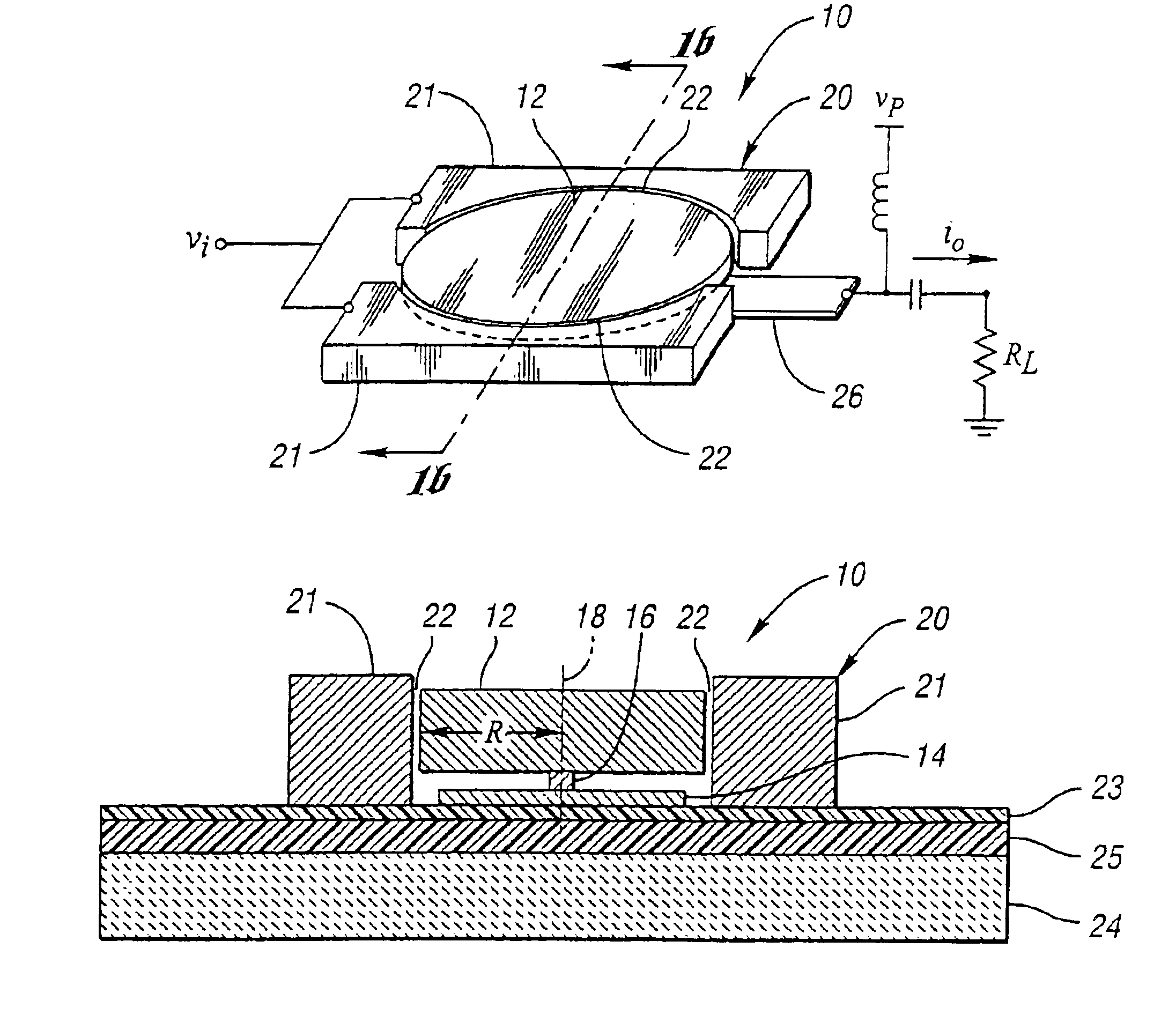
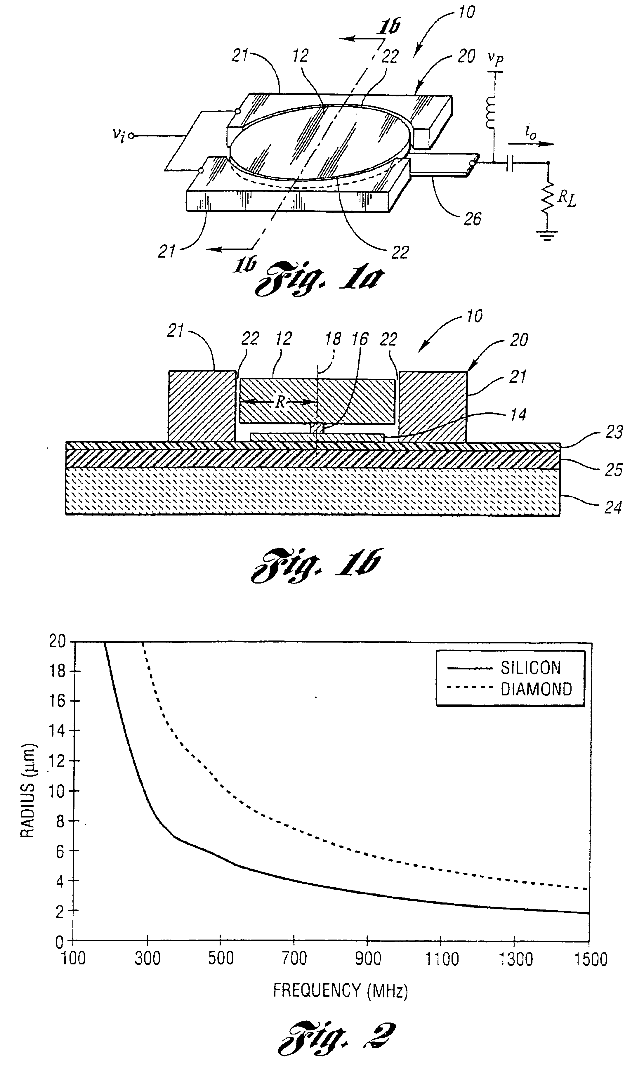
FIGS. 1a and 1b present a preferred embodiment of a micromechanical resonator device of the present invention, generally indicated at 10. In FIG. 1a, the perspective view shows the major features of the preferred embodiment. The resonator device 10 includes a disk 12 supported above a ground plane 14 and supported by a single anchor post 16 at its center 18. A drive electrode structure, generally indicated at 20, surrounds the perimeter of the disk 12, separated by a narrow air gap 22. The electrode structure 20 is split in half to form two input electrodes 21 in order to allow routing to the ground plane 14 and maintain symmetry. In this configuration, the resonator disk 12 is designed to move in a purely radial mode, expanding and contracting along its radius at resonance ideally with no motion perpendicular to a substrate 24 having isolation and passivation layers 23 and 25 or rotation around the anchor point or center 18. In this mode, the center 18 of the disk 12 is a nodal poi...


PUM


Abstract

A micromechanical resonator device and a micromechanical device utilizing same are disclosed based upon a radially or laterally vibrating disk structure and capable of vibrating at frequencies well past the GHz range. The center of the disk is a nodal point, so when the disk resonator is supported at its center, anchor dissipation to the substrate is minimized, allowing this design to retain high-Q at high frequency. In addition, this design retains high stiffness at high frequencies and so maximizes dynamic range. Furthermore, the sidewall surface area of this disk resonator is often larger than that attainable in previous flexural-mode resonator designs, allowing this disk design to achieve a smaller series motional resistance than its counterparts when using capacitive (or electrostatic) transduction at a given frequency. Capacitive detection is not required in this design, and piezoelectric, magnetostrictive, etc. detection are also possible. The frequency and dynamic range attainable by this resonator makes it applicable to high-Q RF filtering and oscillator applications in a wide variety of communication systems. Its size also makes it particularly suited for portable, wireless applications, where, if used in large numbers, such a resonator can greatly lower the power consumption, increase robustness, and extend the range of application of high performance wireless transceivers.

Description

BACKGROUND OF THE INVENTION1. Field of the InventionThis invention relates to micromechanical resonator devices and micromechanical devices utilizing same.2. Background ArtVibrating mechanical tank components, such as crystal and SAW resonators, are widely used for frequency selection in communication sub-systems because of their high quality factor (Q's in the tens of thousands) and exceptional stability against thermal variations and aging. In particular, the majority of heterodyning communication transceivers rely heavily upon the high-Q of SAW and bulk acoustic mechanical resonators to achieve adequate frequency selection in their RF and IF filtering stages and to realize the required low phase noise and stability in their local oscillators. In addition, discrete inductors and variable capacitors are used to properly tune and couple the front end sense and power amplifiers, and to implement widely tunable voltage-controlled oscillators. At present, the aforementioned resonators ...

Claims


Application Information

Patent Timeline
IPC IPC(8): B81B3/00H03H9/00H03H9/50H03H9/46H03H9/24H03H9/02H03H3/00H03H3/013H03H3/007B81B5/00
CPCH03H3/007H03H3/0072H03H3/013H03H9/02362H03H9/2436H03H9/462H03H9/505H03H9/46H03H2009/02527H03H2009/02496H03H2009/02503
Inventor CLARK, JOHN R.NGUYEN, CLARK T.-C.
Owner RGT UNIV OF MICHIGAN
Why Eureka
Try Eureka