Metal fiber-reinforced composite material as well as a method for its production

a technology of reinforced composite materials and metal fibers, which is applied in the direction of transportation and packaging, protective equipment, chemical instruments and processes, etc., can solve the problems of increased danger, low shear strength, and high danger of delamination, and achieves simple and effective procedures.

Inactive Publication Date: 2005-03-01
AIRBUS OPERATIONS GMBH
View PDF15 Cites 33 Cited by
  • Summary
  • Abstract
  • Description
  • Claims
  • Application Information

AI Technical Summary

Benefits of technology

It is particularly advantageous if the metal layers are bonded before they are actually processed or arranged into a sandwich structure. This is a simple and effective procedure for providing the metal layers with the solder alloy. Furthermore, the use of metal layers, which are provided with a solder alloy, proves to be advantageous particularly when the sandwich structure is heated to a temperature of below approximately 600° C. before it is rolled, so that the solder alloy melts and causes the sandwich structure to bond together.

Problems solved by technology

However, it is a disadvantage that, because of its sandwich construction from different materials, the glare material has a low shear strength, so that the danger of delaminating is very high.
This danger is increased by the adhesive used for bonding the sandwich construction, since the adhesive has only a certain, limiting strength.
Consequently, in the case of shear or thrust forces, the load-carrying capacity of the material is limited.
As a result, faces of holes, for example, are not stable.
This means that holes, which are provided in the material, fray or extend under load, so that the shape of the holes is altered in an undesirable manner.
Moreover, because of the sandwich construction described, the glare material is moisture-sensitive and the use of different types of material makes it difficult to recycle the composite material.
It is a further disadvantage that the stiffness of the material in certain directions is limited because of the special orientation of the fibers.
Moreover

Method used


Image

  • Metal fiber-reinforced composite material as well as a method for its production
  • Metal fiber-reinforced composite material as well as a method for its production
  • Metal fiber-reinforced composite material as well as a method for its production

Examples


Embodiment Construction

Formation of a Metal Fiber-Reinforced Composite Material

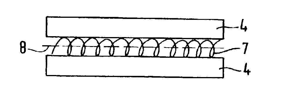
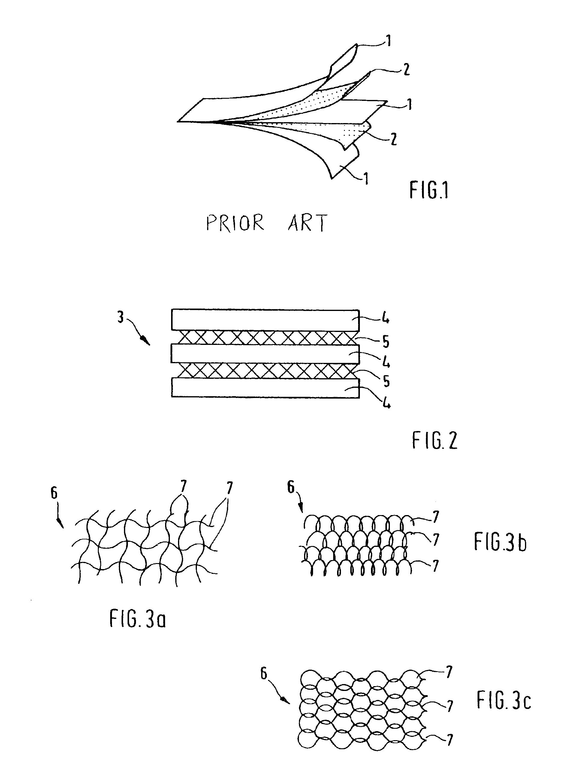
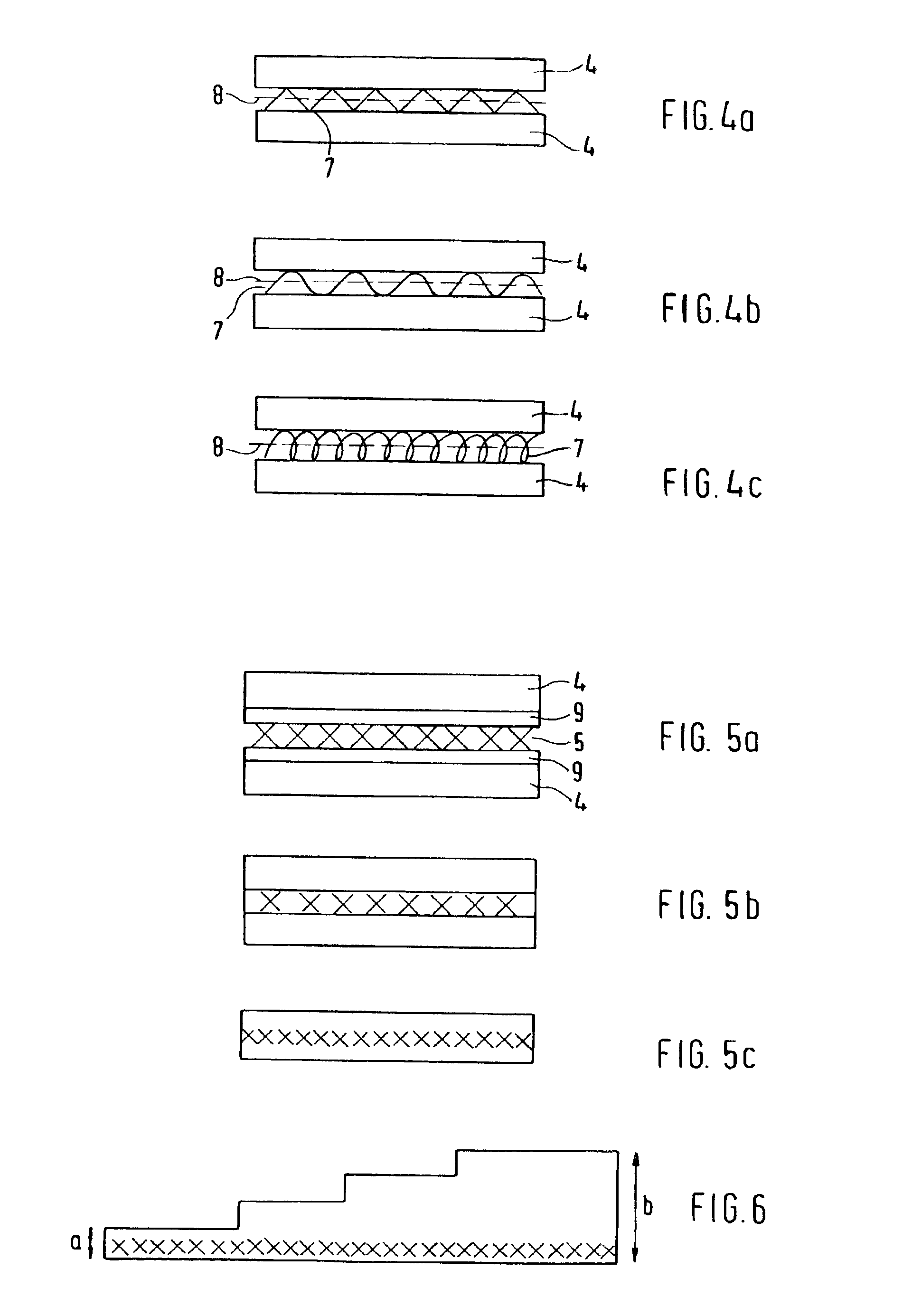
A typical aluminum alloy sheet for aviation is constructed from three layers of sheet aluminum 4 as well as from two reinforcing layers 5. Before they are rolled, the layers of sheet aluminum have a thickness of 4 mm and the reinforcing layers have a thickness of about 0.5 mm so that the composite has a total thickness of about 13 mm. After the rolling, the metal fiber-reinforced composite material has a thickness of approximately 6.5 mm. The reinforcing layers may be disposed at any place within the sandwich structure. FIG. 6 shows a component of the inventive composite material with a step-shaped surface, the thin side surface “a” having a height of about 1.5 mm and the thick side surface “b” a height of about 5 mm. The reinforcing layer “X” is disposed at the bottom, so as not to interfere with the step-shaped processing of the composite. Accordingly, it is possible to construct any tailor-made composite material.

With the he...


PUM

PropertyMeasurementUnit
Strengthaaaaaaaaaa

Abstract

A metal fiber-reinforced composite material can be produced by providing metal layers and reinforcing layers disposed alternately into a sandwich structure, the reinforcing layers containing fibers of a high-strength metallic material, which are disposed in the form of a loose structure between the metal layers, in order to create a material excess of fibers in the reinforcing layers, the sandwich structure being bonded by a thermomechanical process in such a manner, that the fibers are lengthened because of the excess of material, the sandwich structure being bonded.

Description

FIELD OF THE INVENTIONThe present intervention relates to a metal fiber-reinforced composite material as well as to a method for its production.BACKGROUND AND SUMMARY OF THE INVENTIONA large number of metal matrix composite materials are known which contain, as a rule, reinforcing elements in the form of powdery particles or short or long fibers. These elements are partly embedded directly in the metal matrix or bonded to the metal matrix, forming a sandwich structure.Furthermore, in aviation, another composite material which is also referred to as “fiber metal laminate” (FML) is used, the construction of which is described, for example, in the article by J. W. Gunnink, “GLARE: An Improved Damage Tolerance Material”, Proceedings of the 19th European Conference on Materials for Aerospace Applications, Munich, Germany, Dec. 6-8, 2000. The glare material is a sandwich construction and consists of a number of alternating layers of aluminum and glass fiber prepregs, a “prepreg” being a p...

Claims


Application Information

Patent Timeline
IPC IPC(8): B32B15/14B32B15/01B32B15/02F41H5/04F41H5/00
CPCB32B15/01B32B15/017B32B15/02B32B15/14F41H5/045F41H5/0464Y10T428/12861Y10T428/12347Y10T428/12493Y10T428/12736Y10T428/12444Y10T428/12806
Inventor PALM, FRANK
Owner AIRBUS OPERATIONS GMBH
Why Eureka
Try Eureka