

Olefin polymers, method of making, and use thereof
a polymer and polymer technology, applied in the field of polymer compositions, can solve the problems of bimodal resin deficiency, bimodal resins begin to “sag”, and still semi-molten polymers do not have sufficient melt strength, and achieve a constant branch distribution profile and high load melt index
- Summary
- Abstract
- Description
- Claims
- Application Information
AI Technical Summary
Benefits of technology
Problems solved by technology
Method used
Image

Examples
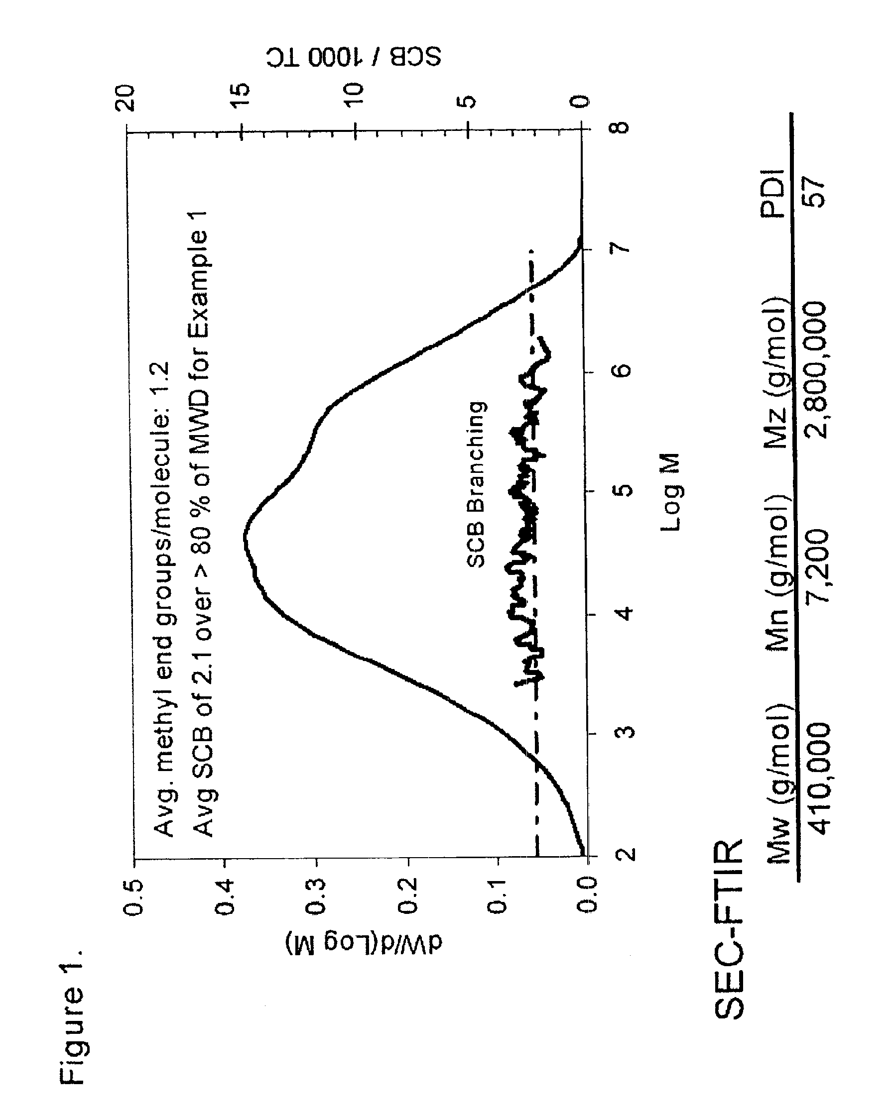
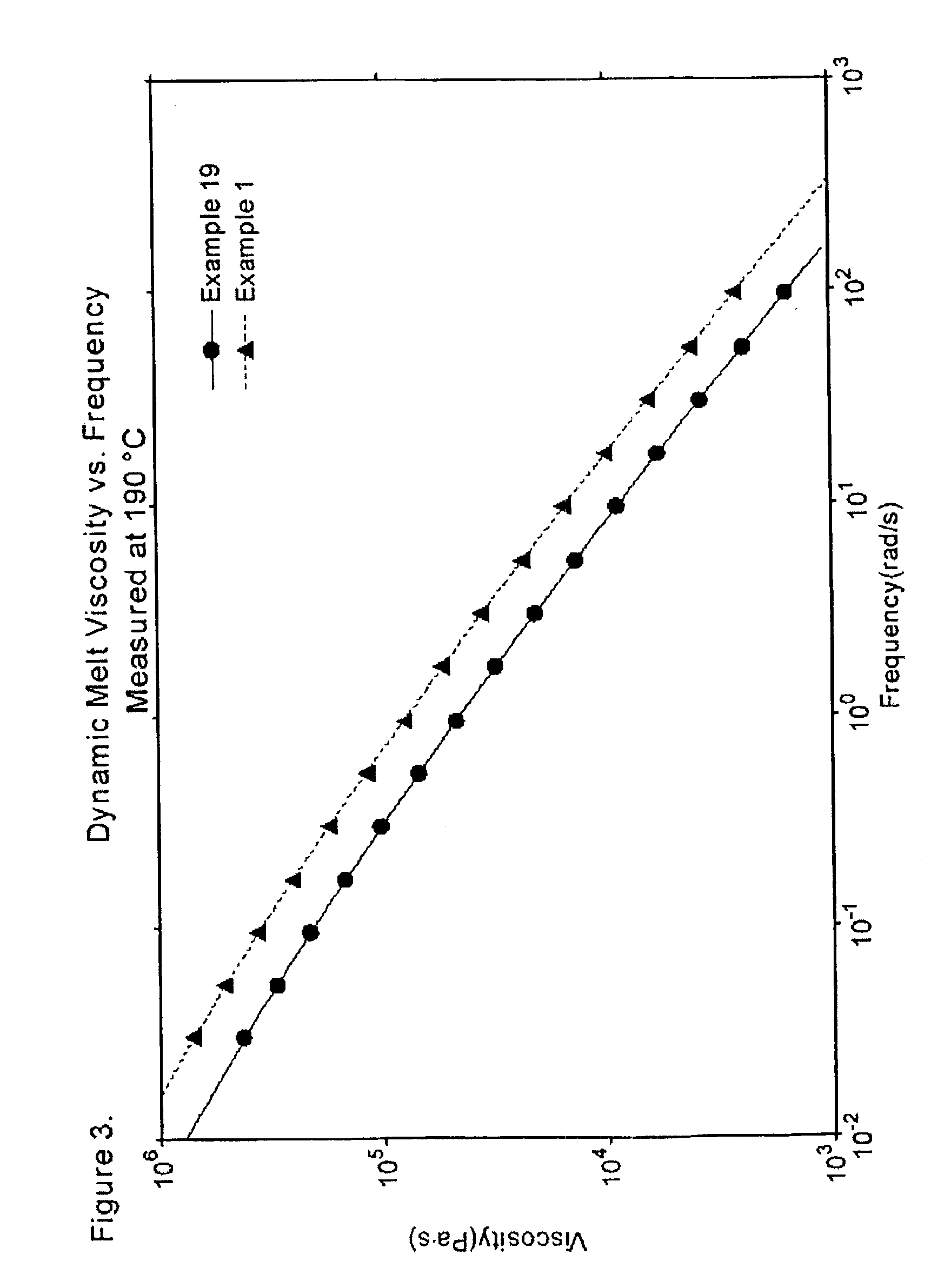
example 1
Catalyst Activation
The above-described catalyst was activated by calcination in dry air at 600° C. In a typical activation batch, about 500 lbs of the catalyst was added to commercial activator consisting of a porous plate inside 42 inch diameter inconel cylinder about 20 feet in height. The catalyst rested on the porous plate, through which dry air was passed at the rate of about 0.2 feet / second (ft / sec) in order to fluidize the bed. The temperature was gradually raised to about 600° C. over a period of about 8-10 hours. Once at 600° C., the activator was allowed to remain at that temperature, while fluidizing, for about another 10 hours. The activated catalyst was then cooled down to about 300° C., at which temperature the activated catalyst was removed from the activator. During the last 2-3 hours of the cool-down period, the fluidization air was replaced by dry nitrogen. After removal from the activator, the catalyst was stored under nitrogen in an air-tight container until its ...
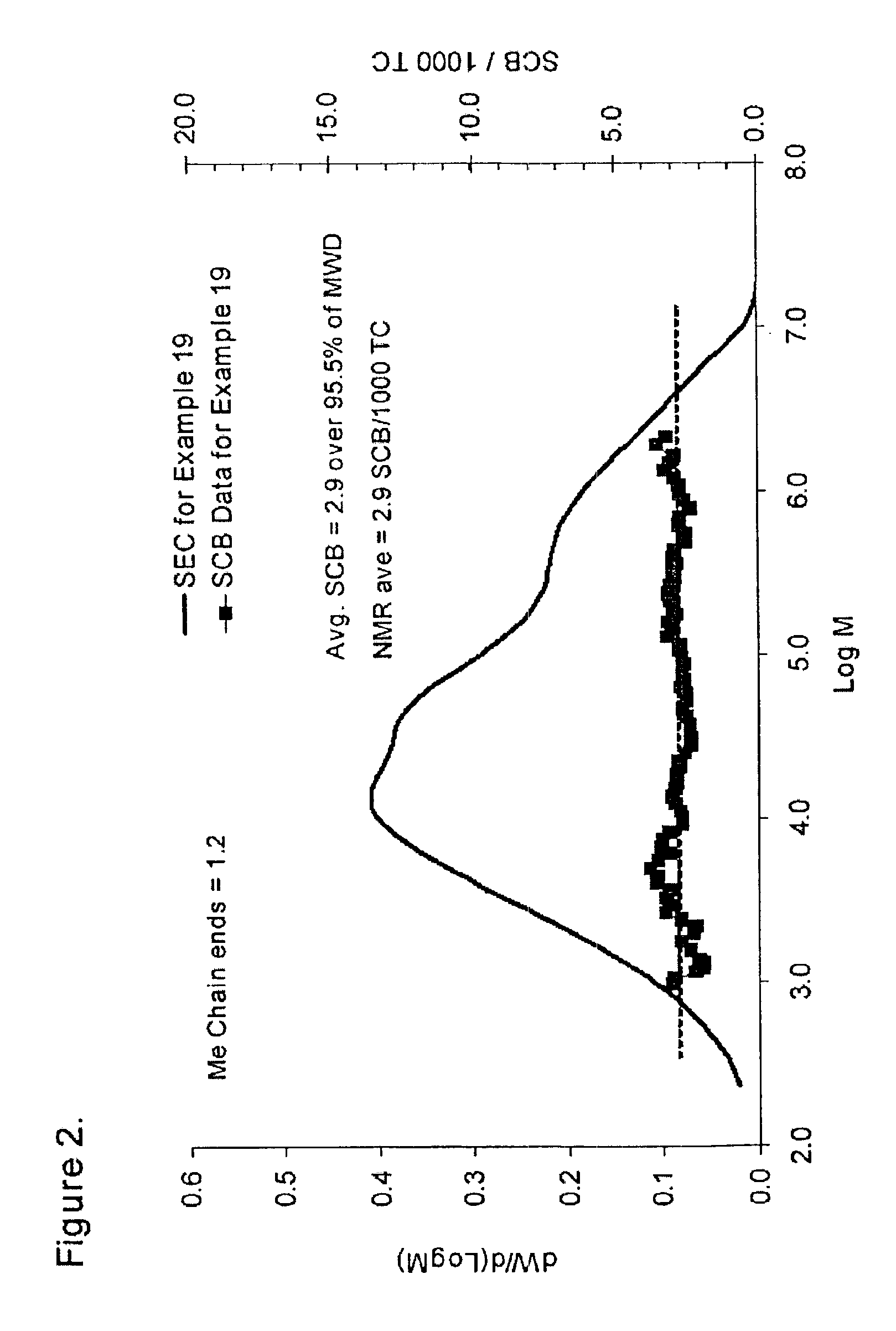
examples 2-19
Catalyst Preparation:
Several runs were made at a pilot plant scale employing the catalyst system of the present invention. The procedure used in Example 1 to prepare the catalyst was also used in these examples, except that the amount of phosphoric acid added to the preparation was adjusted to vary the P / Al molar ratio of the resultant catalyst. Other steps were identical. Catalyst activation was similarly carried out in a fluidized bed in air at about 600° C. in all cases. 1.5 lbs of catalyst was charged to a six-inch diameter cylinder with distributor plate for fluidization. Dry air was used to fluidize the catalyst as the temperature was raised to about 600° C. This process required about eight hours, and the catalyst was allowed to remain fluidizing in dry air at about 600° C. for about another six hours. The catalyst was flushed with dry nitrogen during cool-down and then stored under nitrogen until ready for use.
Ethylene polymers were prepared in Examples 2-19 in...
example 20
This example illustrates the preparation of various catalyst systems used in the following Examples.
Chromium / Aluminophosphate Catalyst Systems
Aluminophosphate catalyst systems were prepared from a concentrated syrup containing aluminum nitrate nonahydrate, ammonium phosphate monobasic, and chromium nitrate. A small amount of water was added, usually about the same amount as the aluminum nitrate, and was warmed to about 40° C. (104° F.) to dissolve the mixture. The aluminum nitrate and aluminum phosphate monobasic were added in an amount needed to yield the desired phosphorus to aluminum mole ratio (P / Al). For example, to achieve a phosphorus to aluminum mole ratio (P / Al) of 0.2 in the final catalyst system, 0.2 moles of ammonium phosphate monobasic were added for each mole of aluminum nitrate nonahydrate. Chromium nitrate was added in an amount needed to yield 1 weight percent chromium on the final product. To this syrup then was added, with rapid and vigorous stirring, concentrated...
PUM
| Property | Measurement | Unit |
|---|---|---|
| Diameter | aaaaa | aaaaa |
| Molar mass | aaaaa | aaaaa |
| Molar mass | aaaaa | aaaaa |
Abstract
Description
Claims
Application Information