

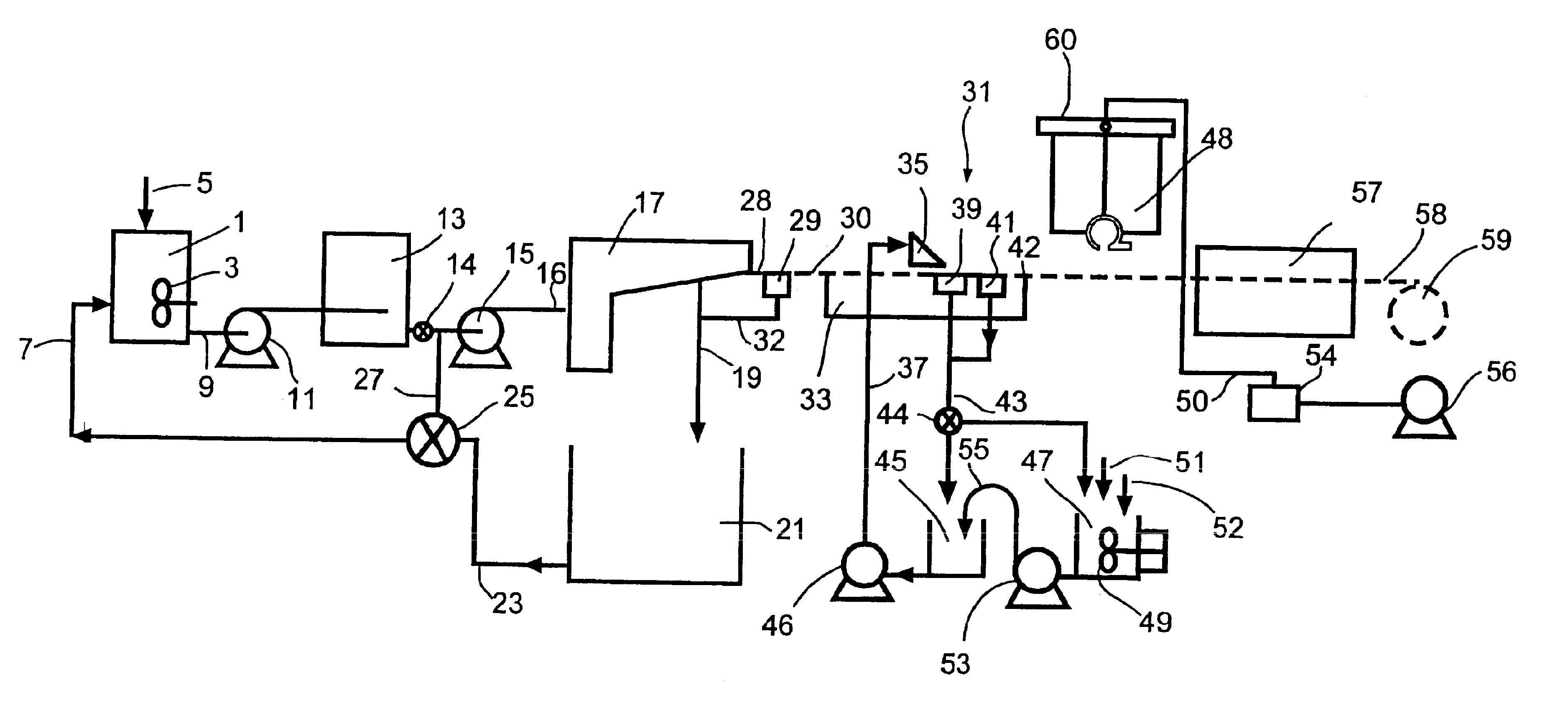
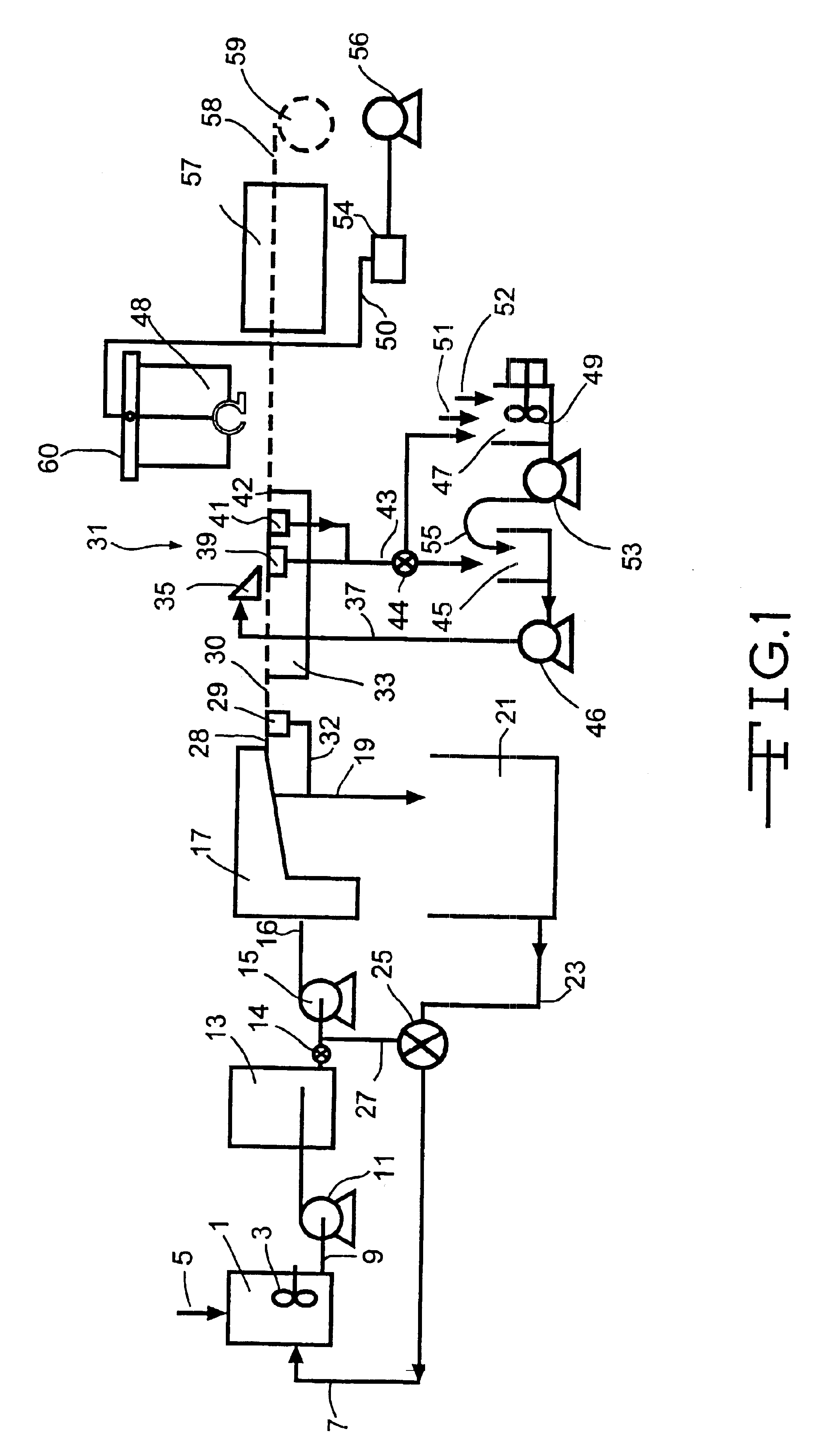
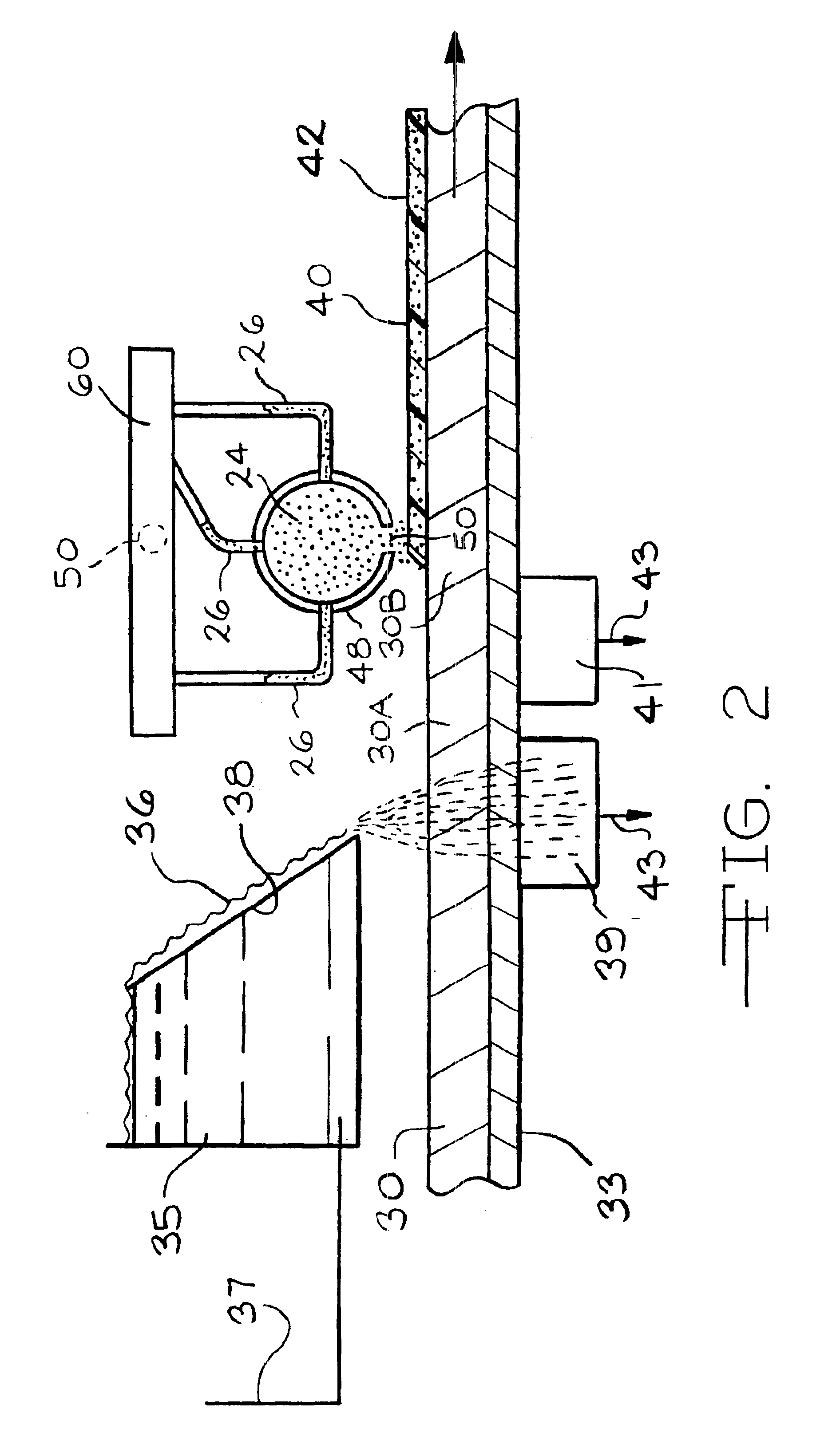
Method of making foam coated mat online
a technology of foam coating and online production, which is applied in the directions of weaving, non-fibrous pulp addition, transportation and packaging, etc., can solve the problems of irritating the hands and arms of workers handling and installing the insulating board products, process breakouts adding to production costs, and difficult folding around the edges of the board, etc., to achieve less expensive, non-abrasive, and large fiber diameter
- Summary
- Abstract
- Description
- Claims
- Application Information
AI Technical Summary
Benefits of technology
Problems solved by technology
Method used
Image

Examples
example 1
A wet web was formed in a conventional wet process on a laboratory wet former simulating a Voith Hydroformer™ line as used and disclosed in U.S. Pat. Nos. 4,637,496 and 5,772,846 using M 117 glass fibers one inch long. A fiber slurry was prepared in a well known manner by adding one inch long E glass type M 117 wet chop glass fiber from Johns Manville International, Inc. having a silane containing chemical sizing on the surface, as is well known, to a known cationic white water containing Natrosol™ thickening agent available from Aqualon, Inc. of Wilmington, Del., and a cationic surfactant C-61, an ethoxylated tallow amine available from Cytec Industries, Inc. of Morristown, N.J., as a dispersing agent to form a fiber concentration of about 0.8 weight percent. After allowing the slurry to agitate for about 5 minutes to thoroughly disperse the fibers, the slurry was metered into a moving stream of the same whitewater to dilute the fiber concentration to a concentration averaging abou...
example 2
Another wet web was formed in the same conventional wet process on a laboratory wet former simulating a Voith Hydroformer™ line as used and disclosed in U.S. Pat. Nos. 4,637,496 and 5,772,846 as used in Example 1. A fiber slurry was prepared in a well known manner by adding 0.75 inch long E glass type K 117 wet chop glass fiber from Johns Manville International, Inc. having a silane containing chemical sizing on the surface, as is well known, to a known cationic white water containing Natrosol™ thickening agent available from Aqualon, Inc. of Wilmington, Del., and a cationic surfactant C-61, an ethoxylated tallow amine available from Cytec Industries, Inc. of Morristown, N.J., as a dispersing agent to form a fiber concentration of about 0.8 weight percent. After allowing the slurry to agitate for about 5 minutes to thoroughly disperse the fibers, the slurry was metered into a moving stream of the same whitewater to dilute the fiber concentration to a concentration averaging about 0....
example 3
Example 2 was duplicated except for the type of foam used and the basis weight of the finished mat which in this example was 1.3 pounds per / 100 sq. ft. Also, a non-foam coated, bindered mat of the same kind as the bindered mat used to make the foam coated mat was made as a control. In this example a fluorpolymer was used. The fluorpolymer used was Sequapel NRL available from Omnova Solutions of Chester, S.C. The properties of fluorpolymer foam coated mat and the control mat were as follows:
Control mat LOI—27.6 percent
Foam coated mat LOI—29.1
Amount of foam addition—about 1.5 wt. percent of finished mat
Permeability of control mat—643
Permeability of foam coated mat—620
Dry tensile strength of control mat—87.1 lbs. / 3 in. width
Dry tensile strength of foam coated mat—73.1 lbs. / 3 in. width
Hot wet tensile of control mat—40.3 lbs. / 3 in. width
Hot wet tensile of foam coated mat—33.9 lbs / 3 in. width
The foam coated mat was tested for repellency to a 50 percent concentration in water isopropyl alc...
PUM
| Property | Measurement | Unit |
|---|---|---|
| Length | aaaaa | aaaaa |
| Length | aaaaa | aaaaa |
| Time | aaaaa | aaaaa |
Abstract
Description
Claims
Application Information