Method for separating substances using a dielectrophoretic apparatus
a dielectrophoretic apparatus and dielectrophoretic technology, applied in the direction of liquid/fluent solid measurement, fluid pressure measurement, peptide, etc., can solve the problems of low detection sensitivity, high throughput of separation processing, and difficulty in reducing processing time, so as to improve the s/n ratio
- Summary
- Abstract
- Description
- Claims
- Application Information
AI Technical Summary
Benefits of technology
Problems solved by technology
Method used
Image
Examples
example 1
Preparation of an Electrode of the Present Invention Formed with a Vacant Space by Etching
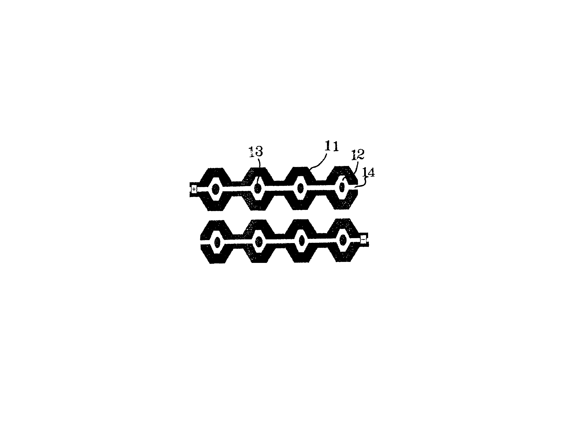
The electrode according to the present invention was prepared by coating a resist on a glass base plate applied with aluminum vapor deposition, then exposing through laminating a photomask having an electrode and vacant space pattern depicted by an electron beam depicting device on the resist, and developing the resist, dissolving a resist film corresponding to the vacant space and portions other than the electrode, and thereafter dipping it into an etching liquid to apply etching to an aluminum surface, and removing the resist remained on the aluminum surface to form an electrode having a vacant space shown in FIG. 13.
The pattern of the vacant space was changed to prepare electrodes 1 to 4 different in length (μm) of a) to e) in FIG. 13. Table 1 shows the length (μm) of a) to e) of electrodes 1 to 4 prepared.
TABLE 1Electrode 1Electrode 2Electrode 3Electrode 4(μm)(μm)(μm)(μm)a14888b8222c551015d...
example 2
Dielectrophoretic Test of Beads on a Hollow Electrode
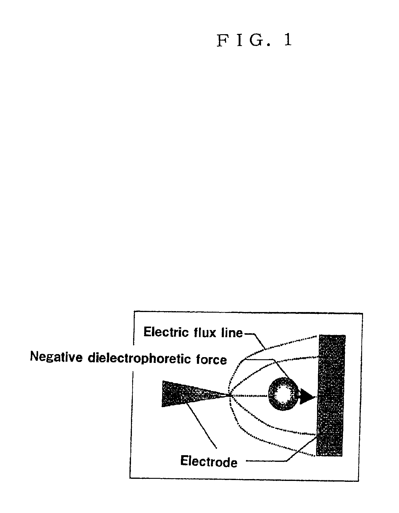
Where beads having a diameter of 1 μm was subjected to dielectrophoresis using a conventional electrode, beads are concentrated (gathered) at a position on the electrode whose field strength is weak. In the design of the electrode prepared in Example 1, the aluminum electrode portion in a region where the beads are gathered are excluded.
A dielectrophoretic test was conducted under the electric field that the beads show the negative dielectrophoresis on the electrode (electrode 2 in Table 1) prepared in Example 1, using beads having a diameter of 1 μm with the fluorescent-labeled surface thereof.
A sample solution with the beads suspended was dropped above the electrode substrate (hollow space), and afterward, a cover glass was put, and observation was made by an optical microscope.
As a result of observation of the dielectrophoretic test, it has been confirmed that the beads were concentrated in the hollow space (vacant space) of th...
reference example 1
Manufacture of Dielectrophoretic Electrode Substrate
A multi-electrode array having a minimum gap of 7 μm, an electrode pitch of 20 μm, and the number of electrodes of 2016 (1008 pairs) was designed, and a photomask according to the design was made for manufacturing the electrode as follows.
On a glass substrate on which aluminum was deposited and to which a photoresist was applied, an electrode pattern as designed was drawn on an electron beam drawing machine, and then the photoresist was developed and the aluminum was etched to make the photomask.
The electrode substrate was manufactured according to the method described in T. Hashimoto, “Illustrative Photofabrication”, Sogo-denshi Publication (1985), as follows.
The photomask thus made was contacted tightly with the aluminum-deposited glass substrate to which a photoresist was applied, and then exposed to the electrode pattern with a mercury lamp. The electrode substrate was manufactured by developing the exposed glass substrate for ...
PUM
| Property | Measurement | Unit |
|---|---|---|
| Force | aaaaa | aaaaa |
| Flow rate | aaaaa | aaaaa |
| Ratio | aaaaa | aaaaa |
Abstract
Description
Claims
Application Information
 - R&D
- Intellectual Property
- Life Sciences
- Materials
- Tech Scout
- Unparalleled Data Quality
- Higher Quality Content
- 60% Fewer Hallucinations
Browse by: Latest US Patents, China's latest patents, Technical Efficacy Thesaurus, Application Domain, Technology Topic, Popular Technical Reports.
© 2025 PatSnap. All rights reserved.Legal|Privacy policy|Modern Slavery Act Transparency Statement|Sitemap|About US| Contact US: help@patsnap.com


