Low-power band-gap reference and temperature sensor circuit

a temperature sensor and low-power band-gap technology, applied in the field of integrated circuit (ic) design, can solve the problems of significantly reducing battery lifetime, increasing chip temperature, and reducing battery life, so as to prolong battery lifetime and data retention time, shorten the refresh cycle time, and increase the temperature

Inactive Publication Date: 2005-04-05
GLOBALFOUNDRIES INC
View PDF7 Cites 94 Cited by
  • Summary
  • Abstract
  • Description
  • Claims
  • Application Information

AI Technical Summary

Benefits of technology

Further, another objective of the present invention is to provide a combined low-voltage, low-power band-gap reference and temperature sensor circuit for providing a band-gap reference parameter and for sensing the temperature of a chip, such as an eDRAM memory unit or CPU chip, using the band-gap reference parameter. The combined sensor circuit is insensitive to supply voltage and a variation in the chip temperature. The power consumption of both circuits encompassing the combined sensor circuit is less than one μW. The combined sensor circuit can be used to monitor local or global chip temperature. The result can be used to (1) regulate DRAM array refresh c

Problems solved by technology

Hence, these circuits consume power causing a reduction in the lifetime of the battery when these circuits are utilized in hand-held, battery-operated devices.
These charge circuits consume power which can significantly reduce battery lifetime.
Additionally, the consumption of power by these charge circuits causes the chip temperature to increase, thereby decreasing the period of time between refresh cycles of the charge circuits.
Further, when these additional circuits are added to the memory unit, they not only consume a great amount of power, but, as a consequence of consuming a great amount of power, they further facilitate the increase in

Method used


Image

  • Low-power band-gap reference and temperature sensor circuit
  • Low-power band-gap reference and temperature sensor circuit
  • Low-power band-gap reference and temperature sensor circuit

Examples


first embodiment

A. A First Embodiment

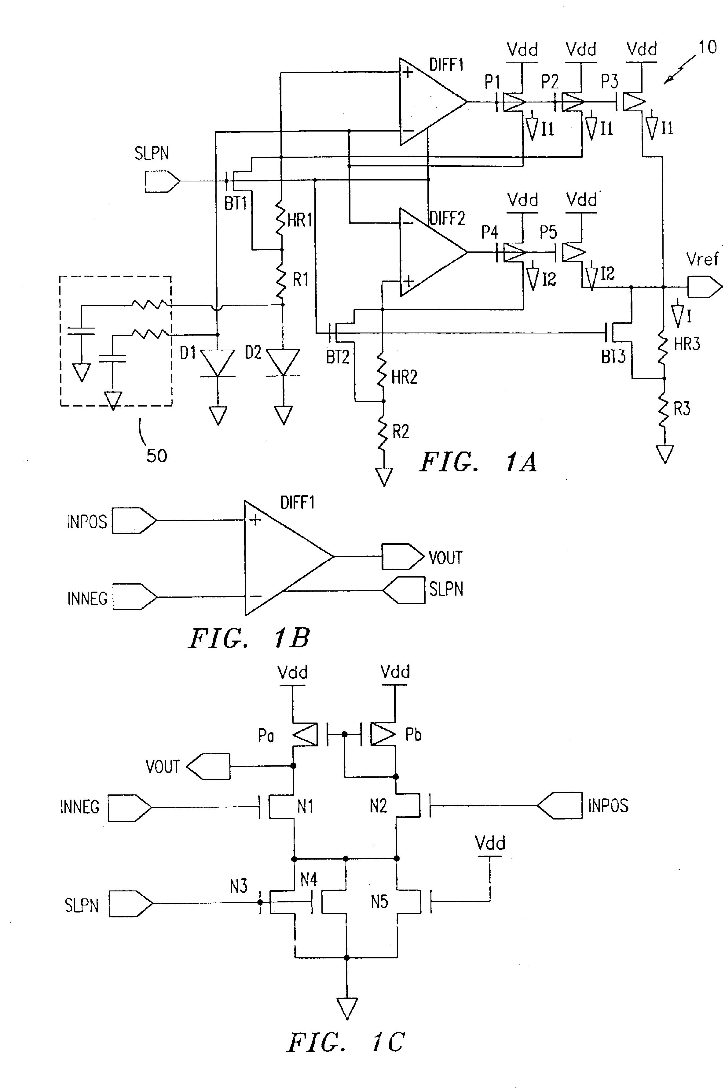
A low-voltage, low-power band-gap reference and temperature sensor circuit can be realized by applying a temperature independent voltage Vref from a band-gap reference circuit as shown by FIGS. 1A and 2 to a temperature sensor circuit as described below. For example, a temperature independent voltage reference Vref from the band-gap reference circuit of FIG. 1A can be applied to an input of a differential amplifier and a temperature dependent reference voltage Vi, where i=1, 2, 3 or 4, obtained from a positive temperature dependent branch or from a negative temperature dependent branch, can be fed to the negative input of the same differential amplifier. When the temperature independent voltage curve intersects with the temperature dependent voltage curve, a predetermined temperature index is read.

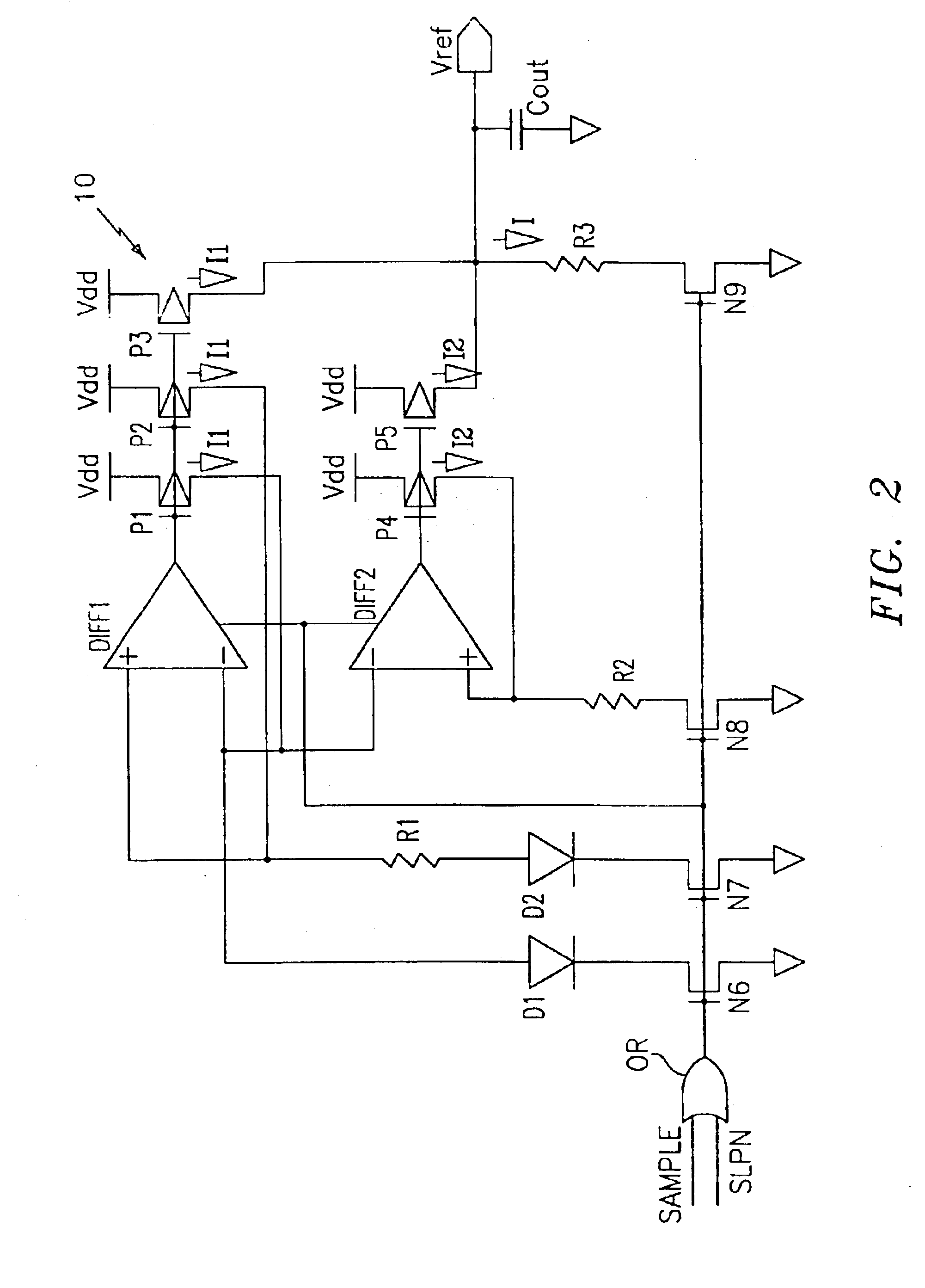
A first embodiment of a band-gap reference and temperature sensor circuit is shown by FIG. 3 and designated generally by reference numeral 20. Sensor circuit 20 includ...

second embodiment

B. A Second Embodiment

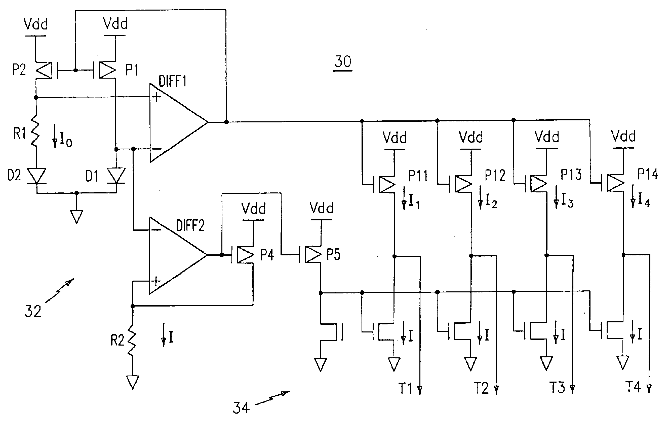
A second embodiment of the band-gap reference and temperature sensor circuit of the present invention is shown by FIG. 5 and designated generally by reference numeral 30. Sensor circuit 30 includes a band-gap reference circuit 32 and a temperature sensing circuit 34. Sensor circuit 30 uses the concept of positive and negative temperature slope current components to perform temperature sensing.

The band-gap reference circuit 32 is almost identical to band-gap reference circuit 10 described above with reference to the first embodiment. It is noted that band-gap reference circuit 32 is schematically illustrated in a different configuration than band-gap reference circuit 20. Further, it is noted that the by-pass transistors BT1, BT2, the high-R resistors HR1, HR2 and the SLPN signal are not shown by FIG. 5, since FIG. 5 is illustrated as operating during normal power operations when these elements are by-passed by a low SLPN signal.

Band-gap reference circuit 32 inc...


PUM


Abstract

A combined low-voltage, low-power band-gap reference and temperature sensor circuit is provided for providing a band-gap reference parameter and for sensing the temperature of a chip, such as an eDRAM memory unit or CPU chip, using the band-gap reference parameter. The combined sensor circuit is insensitive to supply voltage and a variation in the chip temperature. The power consumption of both circuits, i.e., the band-gap reference and the temperature sensor circuits, encompassing the combined sensor circuit is less than one μW. The combined sensor circuit can be used to monitor local or global chip temperature. The result can be used to (1) regulate DRAM array refresh cycle time, e.g., the higher the temperature, the shorter the refresh cycle time, (2) to activate an on-chip or off-chip cooling or heating device to regulate the chip temperature, (3) to adjust internally generated voltage level, and (4) to adjust the CPU (or microprocessor) clock rate, i.e., frequency, so that the chip will not overheat. The combined band-gap reference and temperature sensor circuit of the present invention can be implemented within battery-operated devices having at least one memory unit. The low-power circuits of the sensor circuit extend battery lifetime and data retention time of the cells of the at least one memory unit.

Description

FIELD OF THE INVENTIONThis invention relates to the field of integrated circuit (IC) design. Specifically, it relates to an integrated circuit having a low-voltage, low-power band-gap reference circuit for outputting a reference parameter and a low-voltage, low-power temperature sensor circuit for sensing the on-chip temperature of a semiconductor chip using at least the reference parameter.BACKGROUND OF THE INVENTIONSemiconductor memory units embedded within an integrated circuit (IC) system are arranged in arrays of cells, where each cell stores one bit of information (1 or 0). Generally, in order to maintain the integrity of the data stored within an embedded semiconductor memory unit, such as an embedded dynamic random access memory unit (eDRAM), each cell of the memory unit requires periodic refreshing, since a small charge stored in each cell of the memory unit tends to leak off due to several factors, such as an increase in the temperature of the chip. Accordingly, circuitry ...

Claims


Application Information

Patent Timeline
IPC IPC(8): G01K7/01G05F3/08G05F3/30H01L23/34
CPCG01K7/015G05F3/30H01L23/34H01L2924/0002H01L2924/00
Inventor HSU, LOUIS L.JOSHI, RAJIV V.HOUGHTON, RUSSELL J.
Owner GLOBALFOUNDRIES INC
Why Eureka
Try Eureka