
System and method for bioremediating wastestreams containing energetics

a waste stream and energetic technology, applied in the field of system and method for bioremediation waste stream, can solve the problems of requiring extensive time to complete, and achieve the effects of convenient integration, control, and ease of automation

Inactive Publication Date: 2005-04-12
UNITED STATES OF AMERICA THE AS REPRESENTED BY THE SEC OF THE ARMY
View PDF26 Cites 10 Cited by
  • Summary
  • Abstract
  • Description
  • Claims
  • Application Information

AI Technical Summary

Benefits of technology

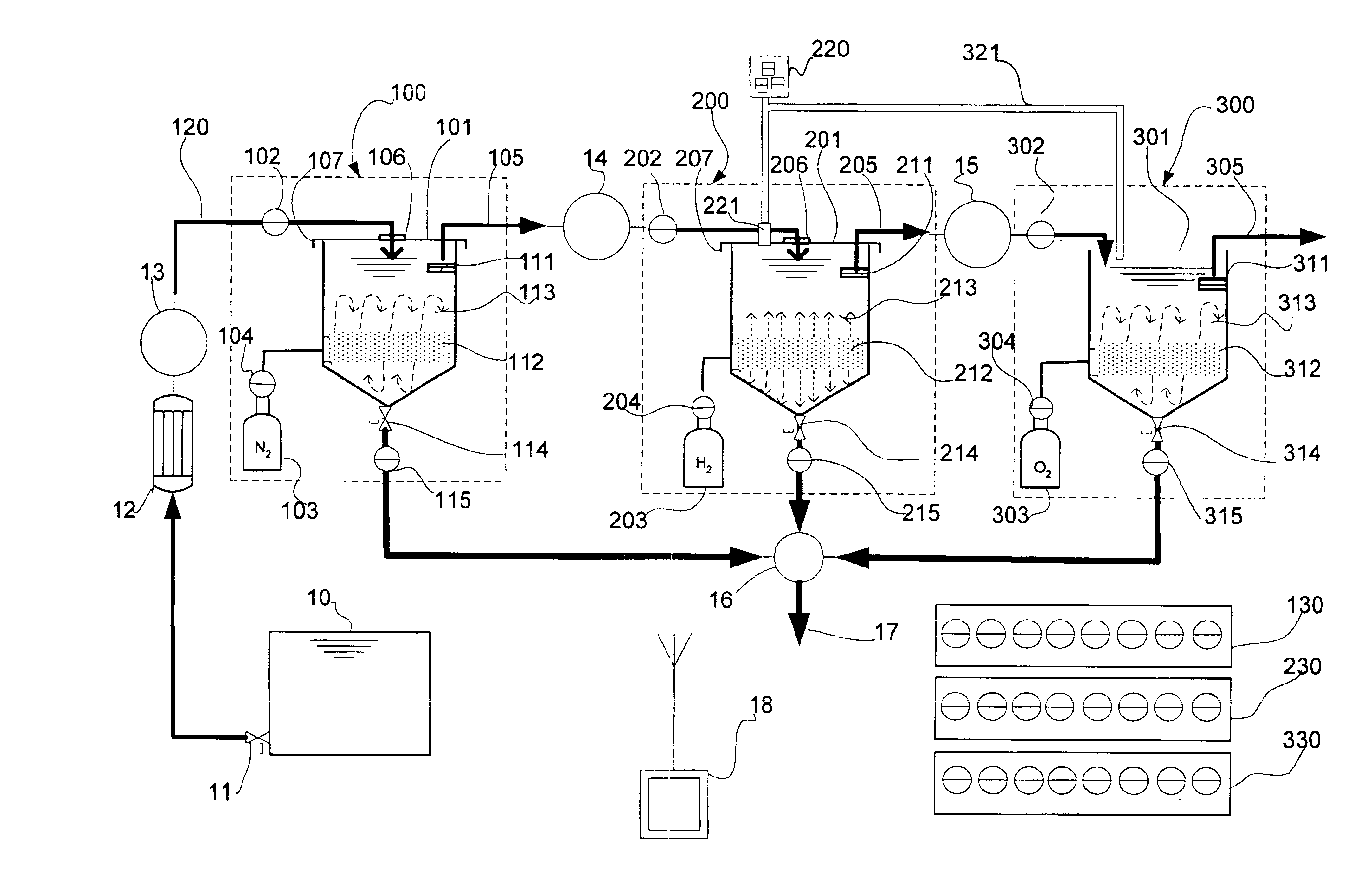
Ideally, the first and second batch reactors are enclosed, i.e., each incorporate a top having a breather, while the final reactor may be open depending on the requirements for maintaining purity of the final effluent or reducing evaporation.
To facilitate control of the process, whether automated, semi-automated or manual, a series of sensors are desirable. Each reactor may need temperature sensors or thermometers, pH sensors, dissolved oxygen (DO) sensors, pressure sensors, fluid level sensors, turbidity meter, electrolytic sensors, flow sensors, or combinations thereof. Information from the sensors should be provided to a display for an operator to monitor as well as to any controller or microprocessor involved in semi-automated or automated control of the process. This display could be a panel of analog or digital meters or a cathode ray tube (CRT) that is able to provide information based on a simple query.
Depending on the size of the reactors, a single pump with a piping and valve system could handle the entire operation on the “fluid” system of the operation while a similar pump, properly set up with the reactors, could handle the sludge pumping. Of course, each reactor could also use its own pump for each of the operations (fluid pumping and sludge pumping), thus reducing the length of the head for any one pumping operation.
Advantages of the system and method include:ease of integration into existing facilities;ease of operation, control, and maintenance, including the process control of flow rate and concentration of hydrogen;ease of automation using programmable logic controllers;flexible operation, including its control over hydraulic retention time;low construction cost;low operation and maintenance costs;relatively short treatment cycle compared to other bioremediation methods;low biological oxygen demand (BOD) of final effluent; andminimal carbon sources required.

Problems solved by technology

Each of these methods involves adding a carbon source and multiple stages that may require extensive time to complete.

Method used


Image

  • System and method for bioremediating wastestreams containing energetics
  • System and method for bioremediating wastestreams containing energetics

Examples


Embodiment Construction

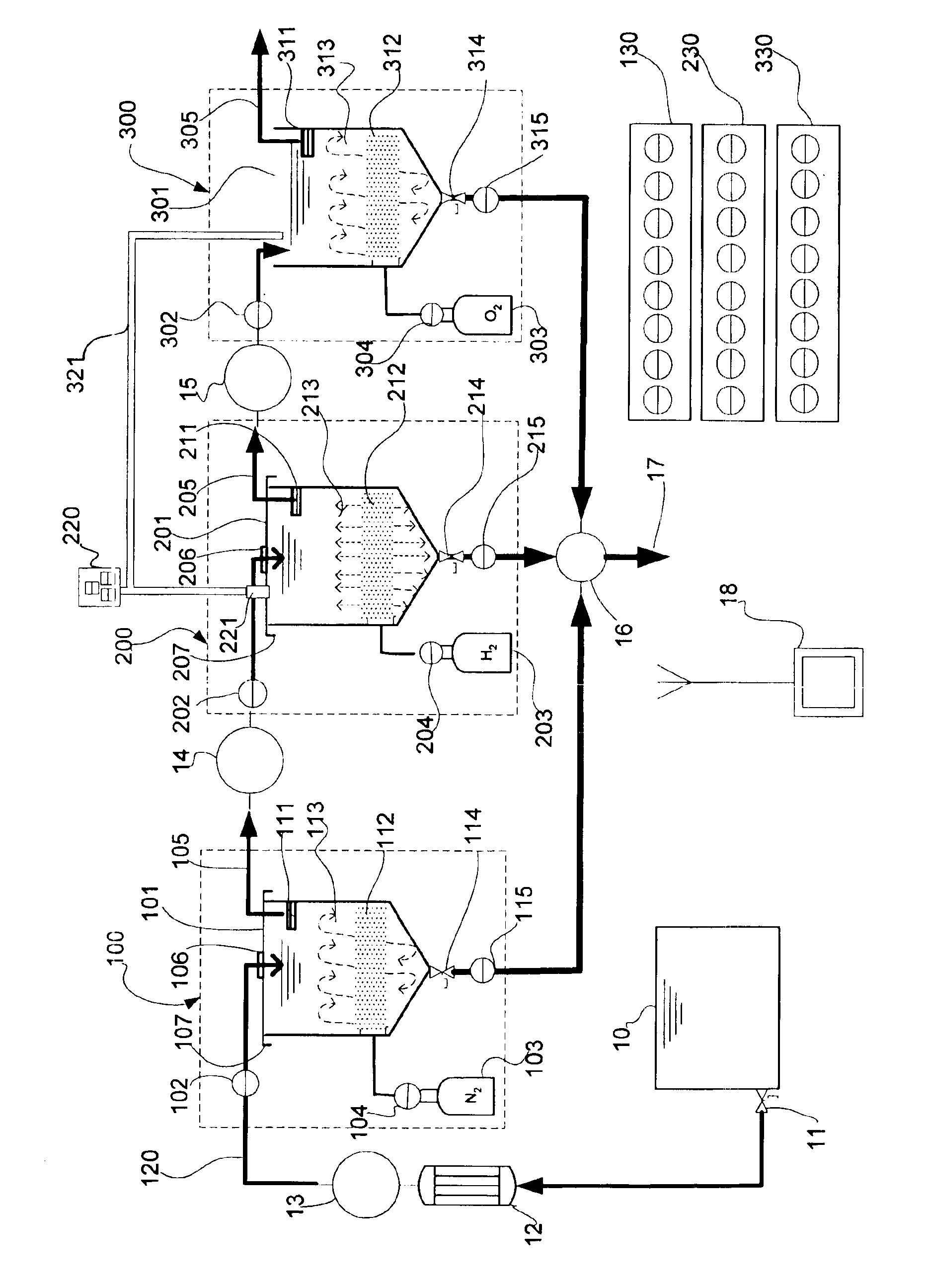
Refer to the FIGURE. Three batch-processing, or SBR, systems 100, 200, 300 are operated in series to breakdown energetics in a waste stream and provide re-cycled water and benign solid waste. A source 10 of waste, such as a holding tank for pink water, provides the waste stream. The waste stream may be released on a pre-specified schedule via a power-actuated control valve 11 in a source tank 10 or other carrier such as a direct pipeline from a processing system. The waste stream may be provided to the first SBR system 100 by a pump 13. The entire treatment process may be controlled by a central controller 18 consisting of one or more microprocessors and necessary communications paths to the various components of the treatment system. This controller 18 may communicate via hardwires, fiber optics, hydraulics, pneumatics, or may use any of a number of wireless technologies such as RE or infrared, or combinations thereof, thus enabling flexibility in upgrading control devices as techn...


PUM


Abstract

A bioremediation system converts a waste stream, at least part of which is a fluid containing energetics, to carbon dioxide (CO2), water, and environmentally benign end products. It uses gas-enhanced sequencing-batch-reactors (SBRs), treating the waste stream in three SBRs seriatim. The first SBR uses a nitrogen purge, the second a hydrogen gas supplement, and the third an oxygen gas or forced air supplement. Each reactor may be supplemented with additives to optimize conditions such as pH, dissolved oxygen, and nutrient level. The system may be implemented under manual control, semi-automated, or fully automated, as needed. A waste stream of consideration is the pink water resultant from munitions fabrication and handling.

Description

FIELD OF THE INVENTIONProvided is a system and method for treating a waste stream, in particular treating a system applying a relatively rapid multi-step bioremediation process to a waste stream containing energetics.BACKGROUNDPink water is wastewater generated from the load-assemble-pack (LAP) operations at U. S. Army Ammunition Plants (AAPs). Constituents of pink water include 2,4,6 trinitrotoluene (TNT), trimethylenetrinitramine (RDX) and cyclotetramethylenetetramine (HMX). Carbon sorption is the conventional method for treating this LAP waste. Using granulated activated carbon (GAC) filters, the waste is passed through the GAC removing the explosive constituents by sorption onto the carbon. This method is non-destructive, i.e., the sorbed molecules of contaminant remain intact chemically. Thus, the process generates spent contaminant-laden GAC filters that require further treatment, to include regeneration of the carbon filter for re-use or safe disposal at the end of the filter...

Claims


Application Information

Patent Timeline
IPC IPC(8): A62D3/00C02F3/12C02F3/00C02F3/30
CPCC02F3/006C02F3/1263C02F3/30C02F2101/003C02F2209/03Y10S588/90C02F2209/11C02F2209/22C02F2209/40C02F2209/42C02F2209/06Y02W10/10
Inventor KIM, BYUNG J.ADRIAN, NEAL R.ARNETT, CLINT M.
Owner UNITED STATES OF AMERICA THE AS REPRESENTED BY THE SEC OF THE ARMY
Learn More