Electrochromic display device and compositions useful in making such devices

a technology of display device and electronic structure, applied in the field of electronic structure display device, can solve the problems of system power (voltage) requirements, lack of flexibility in design options, interference with optical properties, etc., and achieve the effects of low power (voltage) requirements, ease of manufacture, and low cos

Inactive Publication Date: 2005-04-12
AVESO INC
View PDF47 Cites 75 Cited by
  • Summary
  • Abstract
  • Description
  • Claims
  • Application Information

AI Technical Summary

Benefits of technology

Applicants have developed a class of new electrochromic devices to display images. The devices of this invention possess one or more of the following benefits: ease of manufacture, relatively low power (voltage) requirements, ease of attaining multi-color and different color systems without significant redesign, relatively fast response times, and relatively long l

Problems solved by technology

These systems may suffer from a lack of flexibility in design options in that, in order to change from one color system to another, the entire chemistry of the device would need to be changed, i.e., an entirely new redox dye would need to be used.
Thus, the systems have relatively high power (voltage) requirements.
Such gas bubbles will interfere with optical properties and potentially block the electrodes from further reaction.
Possibly, the most significant complicating factor is

Method used


Image

  • Electrochromic display device and compositions useful in making such devices
  • Electrochromic display device and compositions useful in making such devices

Examples


example 1

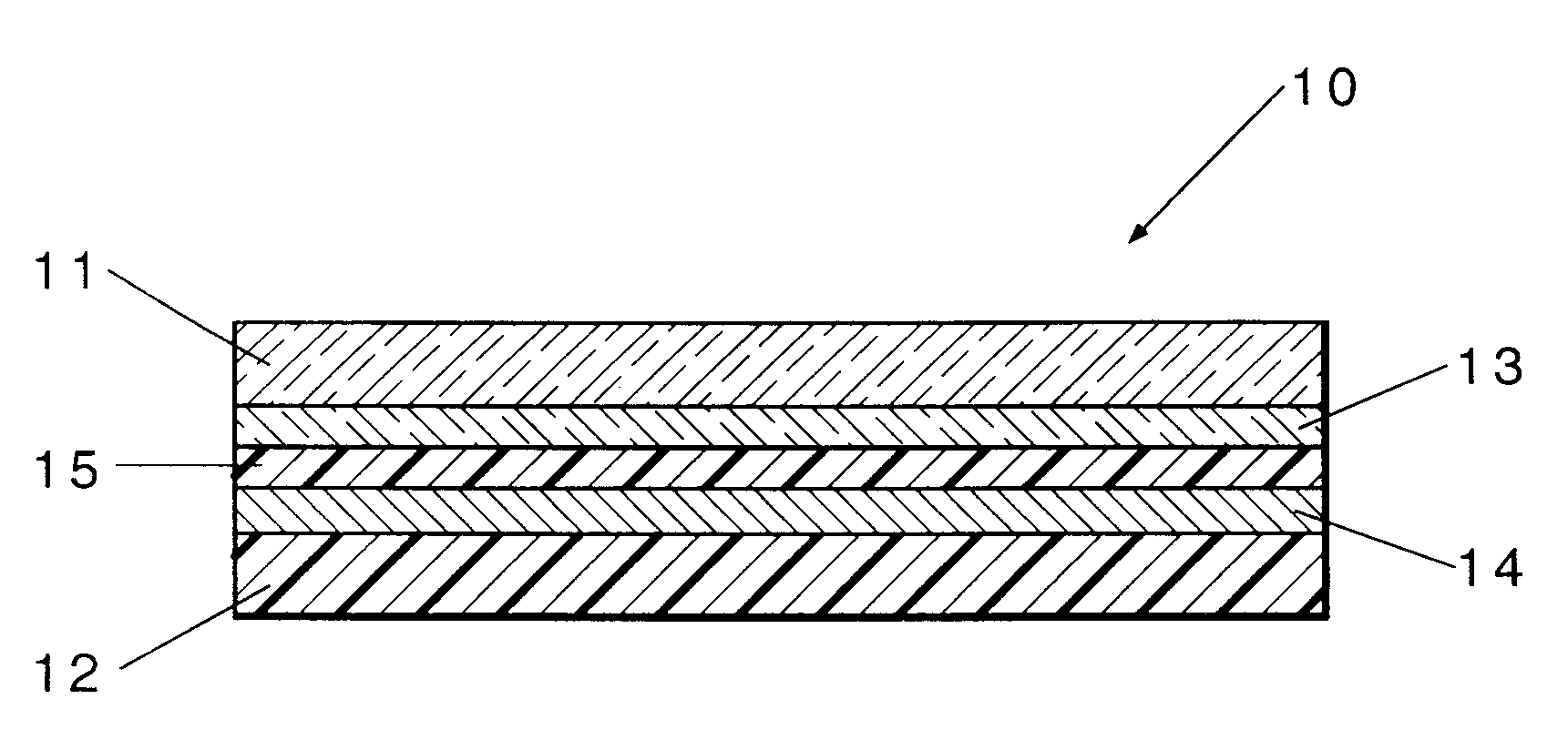
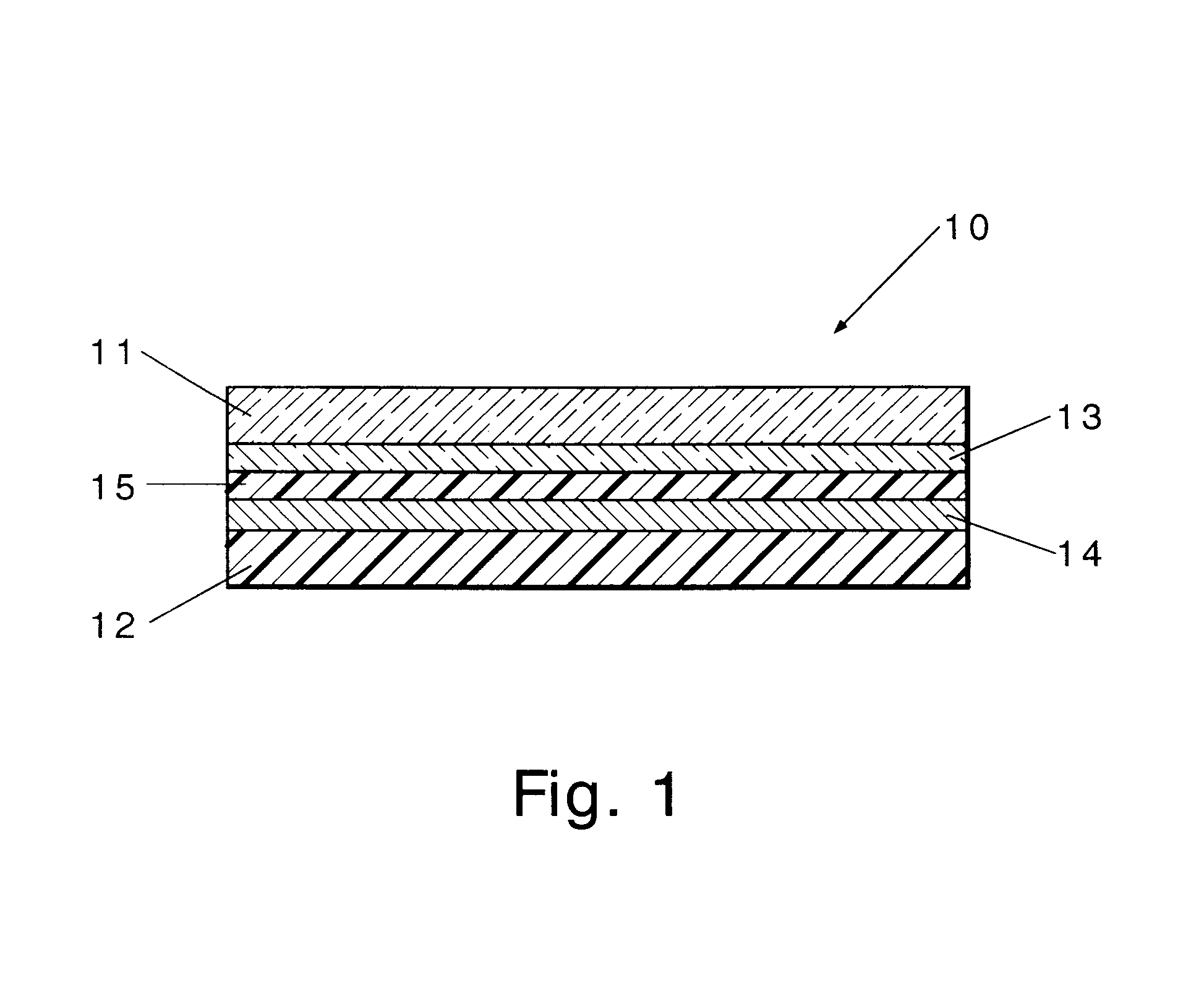
The following reagents were mixed in a small mortar and pestle: 1.0 gram hydroquinone; 1.0 gram titanium dioxide; 0.5 gram bromocrescol purple; 0.5 gram 600,000 MW (number average) polyethylene oxide; 0.5 gram 8,000 MW (number average) polyethylene glycol. The materials were ground well. Next, 1.5 grams of isopropanol was added and mixed well. Finally, 1.9 grams of a saturated aqueous solution of sodium chloride was added and mixed. The material was then allowed to sit covered with Parafilm for 24 hours before use. The material was then pressed between 2 pieces of 100 Ω coated glass and 2 pieces of 100 {tilde over (Ω)} ITO PET plastic (both purchased from Delta Technologies, Stillwater, Minn.), which serves as the electrodes. The electrodes were connected to a variable DC power supply with alligator clips. The material began to image (change from bluish to yellow) beginning at around + / −0.7 volt on both the ITO glass and the ITO coated PET plastic; however, a large change in color w...

example 2

The following reagents were mixed in a small mortar and pestle: 1.0 gram KIO3; 1.0 gram titanium dioxide; 0.5 gram bromocrescol purple; 0.5 gram 1,000,000 MW (weight average) hydroxyethyl cellulose. The materials were ground well. Next, 2.5 grams of an aqueous saturated solution of sodium chloride was added. The composition was greenish in color. The composition was then placed between two pieces of ITO coated glass and plastic (PET), as in Example 1. The material changes from yellow to blue at + / −1.5 volts.

example 3

The same recipe and experiment was made as in Example 1, except ethyl red indicator was used instead of the bromocresol purple dye. The material imaged well from red to yellow at 1.5 volts on both ITO glass and plastic (PET).


PUM


Abstract

The present invention relates to a composition and to a display device having the composition positioned between electrodes. The composition contains: (a) a compound that undergoes a reversible redox reaction to generate a pH gradient between the two electrodes, (b) an indicator dye, (c) a charge transport material, and optionally, (d) a matrix material and (e) an opacifier, and (f) secondary redox couple wherein components (a), (b), and (c) are different from one another and the standard reduction potential of component (a) is less than the standard reduction potential for the other components. Depending on the electric field present between the electrodes, a display image may be generated.

Description

FIELD OF THE INVENTIONThis invention relates to electrochromic display devices and the compositions and materials used in such devices.BACKGROUND OF THE INVENTIONElectrochromism is a term that is used to describe the fact that certain materials change color when exposed to an electric potential. Most electrochromic materials are based on oxidation / reduction (redox) chemistry. Generally, a material is used which is one color in its oxidized form and another color in its reduced form. Based on this principle, windows and mirrors utilizing these materials can be reversibly colored or bleached, as described in U.S. Pat. No. 4,712,879. Most electrochromic displays use a redox dye, which can either be inorganic or organic. For example, a display device using inorganic oxides, such as tungsten and molybdenum oxide, as the electrochromic material is disclosed in U.S. Pat. No. 3,827,784. A display device using an organic dye (viologen) is disclosed in U.S. Pat. No. 3,806,229. These systems m...

Claims


Application Information

Patent Timeline
IPC IPC(8): G02F1/01G02F1/155G02F1/15G02F1/17C09K9/02G02F1/1503
CPCC09K9/02G02F1/176G02F1/155G02F1/1521G02F2001/164G02F1/15G02F1/1503
Inventor VINCENT, JOHN B.BABINEC, SUSAN J.DERMODY, DANIEL L.CHEN, YU
Owner AVESO INC
Why Eureka
Try Eureka