Achromatic fresnel optics based lithography for short wavelength electromagnetic radiations

Inactive Publication Date: 2005-04-26
XRADIA
View PDF10 Cites 46 Cited by
  • Summary
  • Abstract
  • Description
  • Claims
  • Application Information

AI Technical Summary

Benefits of technology

[0012]The present invention seeks to provide a lithography method that overcomes one or more of the above-described shortcomings with a camera based on an optic th

Problems solved by technology

Further reduction in wavelength using current refractive lens-based lithography methods can be extremely difficult and is limited by a lack of suitable materials for making the imaging lenses.
Because of the large number of multilayer mirrors must be used, only a small percentage of the EUV source power is delivered to the wafer, while a large amount flare is added to the exposure.
Consequently the costs of initial tool, replacement, and maintenance are extremely high.
Therefore, compound refractive lenses are not likely t

Method used


Image

  • Achromatic fresnel optics based lithography for short wavelength electromagnetic radiations
  • Achromatic fresnel optics based lithography for short wavelength electromagnetic radiations
  • Achromatic fresnel optics based lithography for short wavelength electromagnetic radiations

Examples


Embodiment Construction

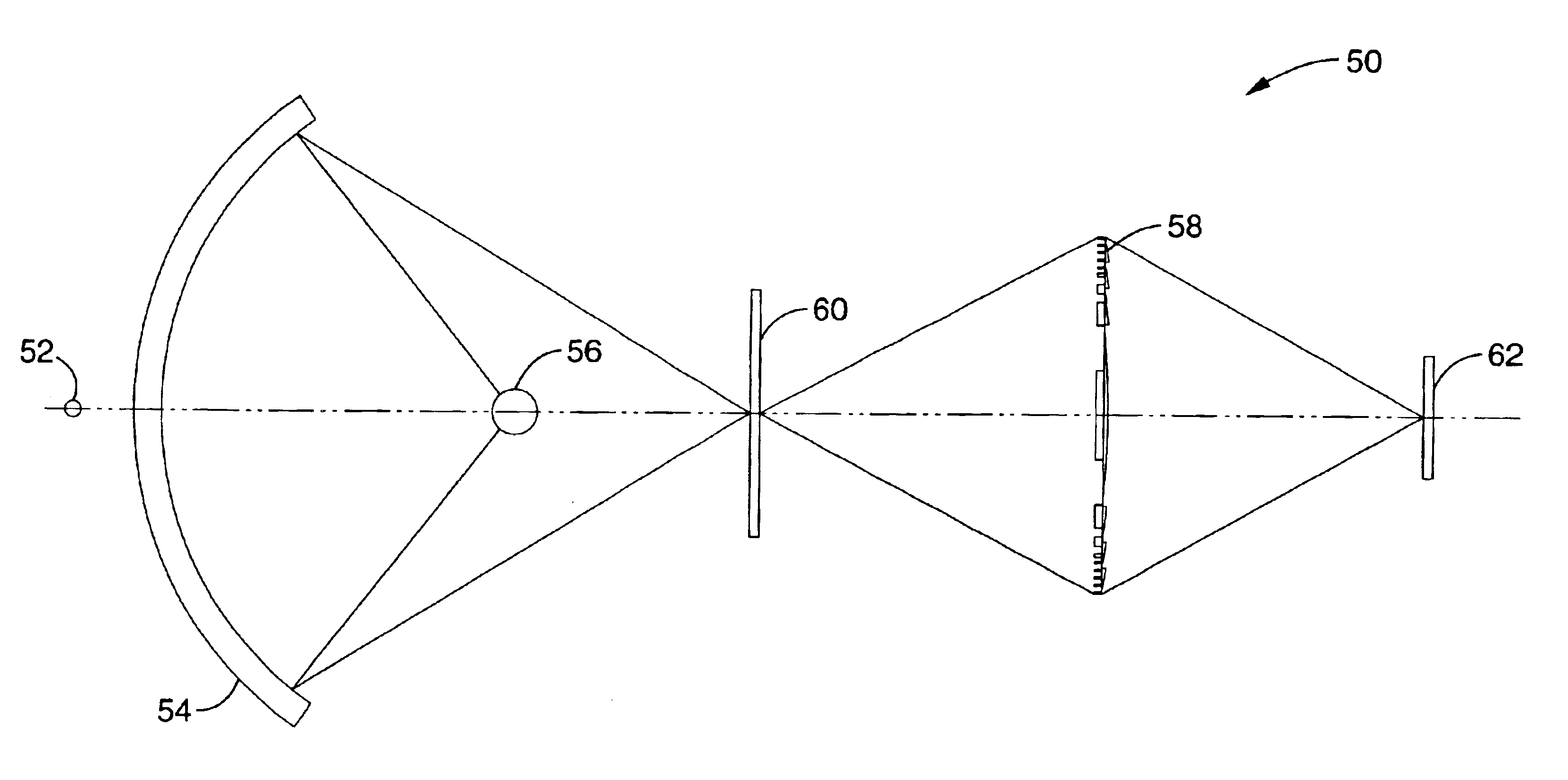
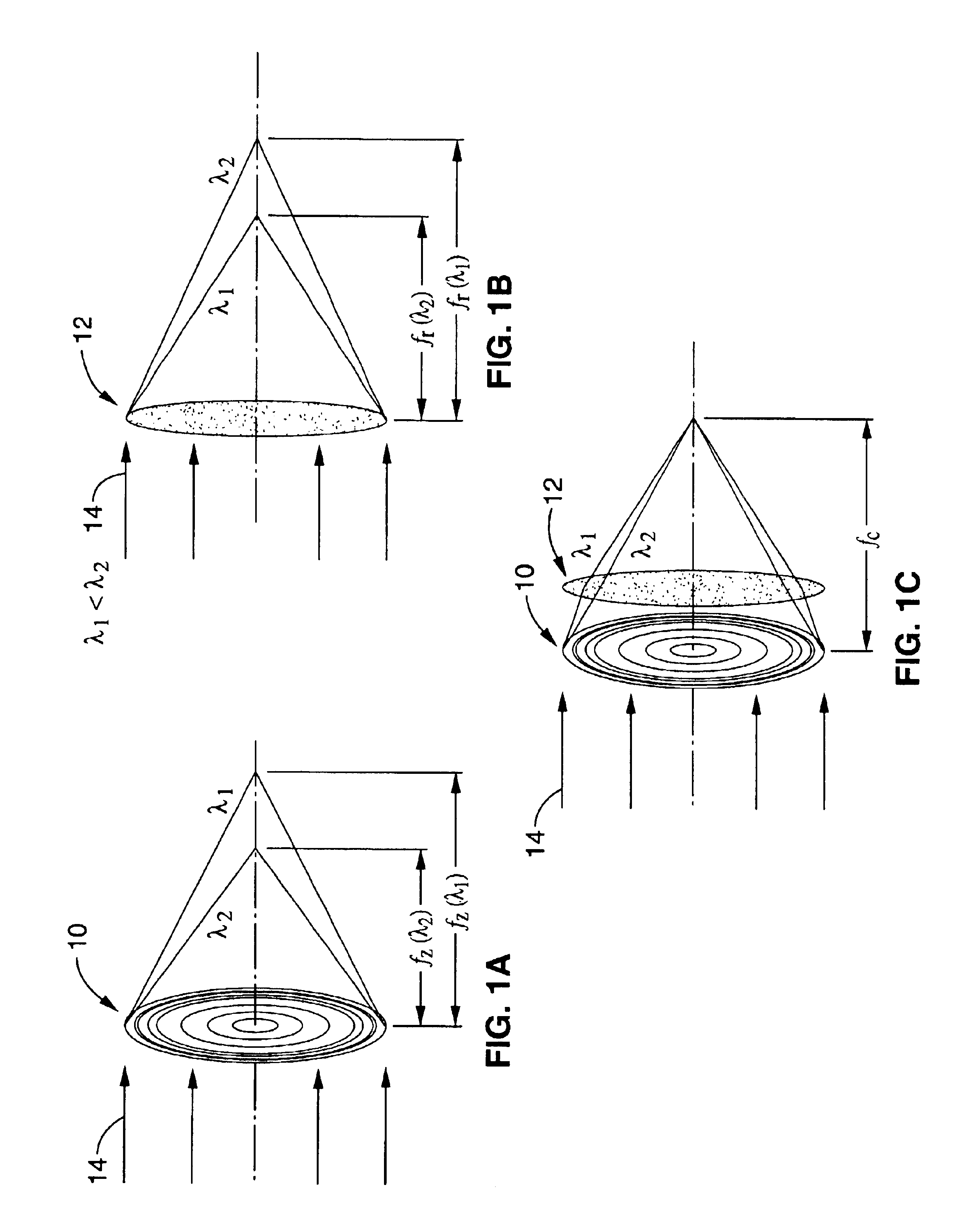
[0040]The preferred embodiments of lithography methods and systems based on an achromatic Fresnel objective, or AFO lens, according to the present invention will now be described. The inventive AFO combines a diffractive Fresnel zone plate for high-resolution image transfer, and a refractive Fresnel lens for chromaticity correction. It can achieve the demonstrated high resolution of zone plates, with the spectral bandpass of multilayer-coated optics. An AFO lithography (AFOL) system according to the present invention is capable of sub-30 nm patterning over an axially symmetric printing field of many square millimeters. The calculated maximum throughput of the imaging system consisting of a condenser and an AFO camera is >20%. The AFOL's axially symmetric transmission imaging system is similar to that of the current generation lithography technology and, therefore, it may be considered as its ultimate extension.

[0041]It will be appreciated that a Fresnel zone plate is a diffractive i...


PUM


Abstract

A lithography apparatus having achromatic Fresnel objective (AFO) that combines a Fresnel zone plate and a refractive Fresnel lens. The zone plate provides high resolution for imaging and focusing, while the refractive lens takes advantage of the refraction index change properties of appropriate elements near absorption edges to recombine the electromagnetic radiation of different energies dispersed by the zone plate. This compound lens effectively solves the high chromatic aberration problem of zone plates. The lithography apparatus allows the use of short wavelength radiation in the 1-15 nm spectral range to print high resolution features as small as 20 nm.

Description

CROSS-REFERENCE TO RELATED APPLICATIONS[0001]This application is a continuation-in-part of copending U.S. application Ser. No. 10 / 134,026 filed on Apr. 25, 2002, incorporated herein by reference, which claims priority from U.S. provisional application Ser. No. 60 / 337,752 filed on Nov. 9, 2001, incorporated herein by reference. This application also claims priority from U.S. provisional application Ser. No. 60 / 338,362 filed on Nov. 9, 2001 and incorporated herein by reference.STATEMENT REGARDING FEDERALLY SPONSORED RESEARCH OR DEVELOPMENT[0002]Not ApplicableREFERENCE TO A COMPUTER PROGRAM APPENDIX[0003]Not ApplicableBACKGROUND OF THE INVENTION[0004]1. Field of the Invention[0005]The present invention pertains generally to lithography, and more specifically to lithography methods using short wavelength electromagnetic radiation.[0006]2. Description of the Background Art[0007]Lithography has been the key enabling technology for the steady performance improvement in semiconductor integr...

Claims


Application Information

Patent Timeline
IPC IPC(8): G02B27/42G02B3/08G03F7/20G02B27/44
CPCG02B3/08G02B27/4211G03F7/70316G02B27/4222G03F7/70308G02B27/4216
Inventor YUN, WENBINGWANG, YUXINNILL, KENNETH W.
Owner XRADIA
Why Eureka
Try Eureka