Fuel reformer device

a fuel reformer and fuel technology, applied in the direction of combustible gas production, electrochemical generators, sustainable manufacturing/processing, etc., can solve the problems of oxidation reaction to proceed, uneven temperature distribution catalyst deterioration, etc., and achieve the effect of simplifying the structure of fuel reformer devices

Inactive Publication Date: 2005-05-03
TOYOTA JIDOSHA KK
View PDF18 Cites 23 Cited by
  • Summary
  • Abstract
  • Description
  • Claims
  • Application Information

AI Technical Summary

Benefits of technology

[0061]In the fuel reformer device of this arrangement, the copper-containing catalyst is used to accelerate the oxidation reaction of methanol. Unlike the prior art technique that uses platinum or another known oxidation catalyst to accelerate the oxidation reaction, the oxidation reaction proceeding in the presence of the copper-containing

Problems solved by technology

The method of supplying oxygen as well as methanol and steam to the fuel reformer device and utilizing the thermal energy generated by the oxidation reaction for the steam reforming reaction, however, has a drawback, that is, an uneven temperature distribution inside the fuel reformer device. FIG. 38 is a graph showing a temperature distribution inside the fuel reformer device that receives supplies of oxygen as well as methanol and steam and causes the oxidation reaction to proceed in parallel with the steam reforming reaction.
Formation of the peak in the temperature distribution or the excessive temperature rise inside the fuel reformer device results in some drawbacks, for example, deterioration of the catalyst and formation of by-products.
One problem is deterioration of the catalyst.
The use of the Cu—Zn catalyst at high tem

Method used


Image

  • Fuel reformer device
  • Fuel reformer device
  • Fuel reformer device

Examples


first embodiment

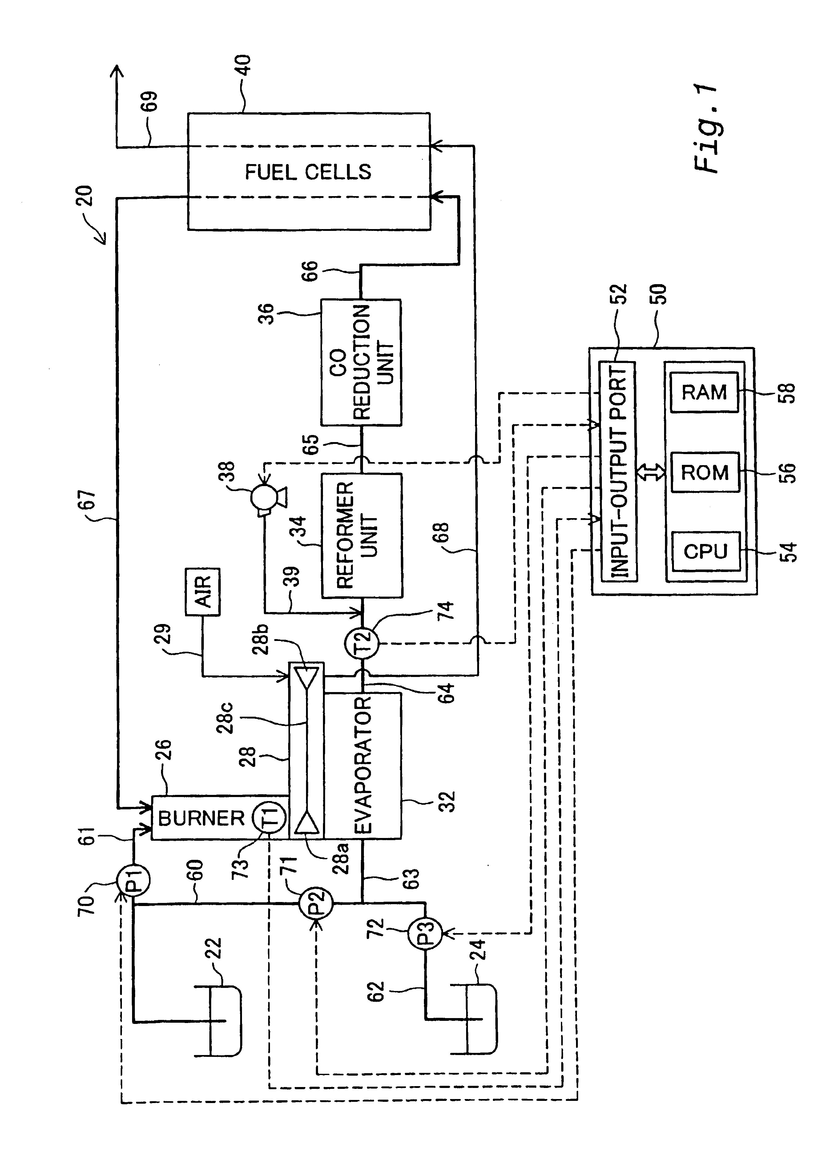
[0100]In order to clarify the configurations, the functions, and the advantages of the present invention discussed above, some modes of carrying out the present invention are described below as preferred embodiments. FIG. 1 schematically illustrates the structure of a fuel cells system 20 including a reformer unit in the present invention. The fuel cells system 20 includes, as primary constituents, a methanol reservoir 22 that stores methanol therein, a water reservoir 24 that stores water therein, a burner 26 that generates a combustion gas, a compressor unit 28 that compresses the air, an evaporator 32 that is coupled with the burner 26 and the compressor unit 28, a reformer unit 34 that produces a gaseous fuel through a reforming reaction, a CO reduction unit 36 that reduces concentration of carbon monoxide (CO) included in the gaseous fuel, fuel cells 40 that generate an electromotive force through electrochemical reactions, and a control unit 50 that is constructed by a compute...

second embodiment

[0140]In the structure of the second embodiment, the catalytic layer 96 using the binder that contains the material having the high thermal conductivity is formed on the honeycomb base member made of the stainless steel plate having the excellent thermal conductivity. Both the catalytic layer 96 and the stainless steel plate 94 conduct heat from the upper stream side to the lower stream side. This effectively attains the high efficiency of heat conduction. In one modified structure, the catalytic layer 96 may be formed on the ceramic honeycomb base member. In another modified structure, the catalyst may be mixed with a binder having the high thermal conductivity, formed to pellets, and packed into the reformer unit. These modified structures also assure the effects caused by the enhanced thermal conductivity from the upper stream side to the lower stream side.

[0141]The structure of suppressing the activity of the oxidation reaction on the upper stream side by making the existing qua...

third embodiment

[0145]In the structure of the third embodiment, the quantity of the catalyst carried on the reformer unit 100 is varied in two stages. The quantity of the catalyst may, however, be varied in three or more stages. The effects discussed above are attained by reducing the quantity of the catalyst carried on the upper stream side. The arrangement of making the smaller quantity of the catalyst carried on the upper stream side and regulating the number of the stages in which the quantity of the catalyst is varied enables the further homogenization of the internal temperature of the reformer unit and enhances the effects discussed above.

[0146]In the structure of the third embodiment, the steam reforming reaction and the oxidation reaction are accelerated by the identical Cu—Zn catalyst. In a modified structure, the steam reforming reaction and the oxidation reaction may be accelerated by different catalyst. In the latter case, the arrangement reduces only the quantity of the catalyst for a...


PUM

PropertyMeasurementUnit
Temperatureaaaaaaaaaa
Areaaaaaaaaaaa
Velocityaaaaaaaaaa

Abstract

The present invention is directed to a fuel reformer device that produces a hydrogen rich gas from a hydrocarbon and steam. The steam reforming reaction that produces the hydrogen rich gas from the hydrocarbon and steam is endothermic. A known technique supplies heat required for the steam reforming reaction by an exothermic oxidation reaction proceeding in parallel with the steam reforming reaction. This known technique may, however, cause an excessive temperature rise in an area of the vigorous oxidation reaction in the fuel reformer device.
A reformer unit 34 including a Cu—Zn catalyst receives a supply of a crude fuel gas containing the air flown through a second fuel supply conduit 64. The crude fuel gas is subjected to the steam reforming reaction and the oxidation reaction proceeding inside the reformer unit 34. A resulting hydrogen rich gaseous fuel is discharged to a third fuel supply conduit 65. The reformer unit 34 includes an upper stream reaction unit 80 and a lower stream reaction unit 81. Both the reaction units 80 and 81 have honeycomb structures, wherein the total sectional area of the flow path in the upper stream reaction unit 80 is made smaller than the total sectional area of the flow path in the lower stream reaction unit 81. This arrangement causes the gas flowing through the reformer unit 34 to have the higher flow velocity on the upstream side than on the downstream side. The higher flow velocity on the upstream side extends the area of the vigorous oxidation reaction to the lower stream portion and enables the heat generated on the upstream side to be effectively transmitted to the lower stream portion. This arrangement thus effectively prevents an excessive temperature rise on the upstream side.

Description

TECHNICAL FIELD[0001]The present invention relates to a fuel reformer device, and more specifically a fuel reformer device that produces a hydrogen rich gas from a hydrocarbon and steam.BACKGROUND ART[0002]The fuel reformer device that produces the hydrogen rich gas from a hydrocarbon and steam is a known device used to supply a gaseous fuel to fuel cells. The fuel cells convert the chemical energy of a fuel into electrical energy not via mechanical energy or thermal energy but directly, and thus attain a high energy efficiency. In the fuel cells, a gaseous fuel containing hydrogen is supplied to anodes thereof, whereas an oxidizing gas containing oxygen is supplied to cathodes thereof. The fuel cells generate an electromotive force through electrochemical reactions proceeding at both the electrodes. The following equations define the electrochemical reactions proceeding in the fuel cells. Equation (1) represents a reaction proceeding at the anodes, and Equation (2) represents a rea...

Claims


Application Information

Patent Timeline
IPC IPC(8): B01J8/04B01J19/24B01J8/10B01J8/08B01J8/00B01J8/06B01J8/02B01B1/00C01B3/32C01B3/00C01B3/38H01M8/06C10G35/04
CPCB01B1/005B01J8/001B01J8/0207B01J8/0278B01J8/0285B01J8/0403B01J8/0446B01J8/0492B01J8/0496B01J8/067B01J8/085B01J8/087B01J8/10B01J19/2475B01J19/2485C01B3/323C01B3/38C01B3/382C01B3/386H01M8/0612H01M8/0631B01J2208/00061B01J2208/00088B01J2208/00106B01J2208/00309B01J2208/00362B01J2208/00548B01J2208/021B01J2219/00063B01J2219/00069B01J2219/00117B01J2219/00164B01J2219/002B01J2219/00213B01J2219/0022B01J2219/00231B01J2219/182C01B2203/0233C01B2203/0244C01B2203/044C01B2203/047C01B2203/066C01B2203/0811C01B2203/0822C01B2203/0827C01B2203/0833C01B2203/0844C01B2203/0866C01B2203/0877C01B2203/1017C01B2203/1023C01B2203/1035C01B2203/1041C01B2203/1064C01B2203/1076C01B2203/1082C01B2203/1223C01B2203/1235C01B2203/1288C01B2203/141C01B2203/142C01B2203/143C01B2203/1604C01B2203/1619C01B2203/1652C01B2203/1661C01B2203/169C01B2203/1695C01B2203/80C01B2203/82H01M2300/0082Y02E60/50Y02P20/10H01M8/06H01M8/04
Inventor TAKI, MASAYOSHIMIZUNO, SEIJIOZAKI, TOSHIAKIKAWAHARA, TATSUYAKINOSHITA, KATSUHIKONEGISHI, YOSHIMASA
Owner TOYOTA JIDOSHA KK
Why Eureka
Try Eureka