Eureka AIR delivers breakthrough ideas for toughest innovation challenges, trusted by R&D personnel around the world.

Lithographic printing plate precursor

a technology of lithographic printing plate and precursor, which is applied in the direction of photosensitive materials, instruments, photomechanical equipment, etc., can solve the problems of reduced sensitivity, low hydrophilicity of organic materials, and exothermic loss, and achieve excellent smearing resistance and press life, improve residual color and residual film, and maintain sensitivity

Inactive Publication Date: 2005-05-10
FUJIFILM CORP
View PDF18 Cites 45 Cited by
  • Summary
  • Abstract
  • Description
  • Claims
  • Application Information

AI Technical Summary

Benefits of technology

[0022]An object of the present invention is to provide a lithographic printing plate precursor capable of getting over the drawbacks of prior art techniques, improving residual color and residual film with maintaining sensitivity, and excellent in smearing resistance and press life.
[0023]Another object of the present invention is to provide a lithographic printing plate precursor capable of using a heat efficiently in image-forming, high in sensitivity, excellent in press life, and free from the generation of smearing on a non-image area.
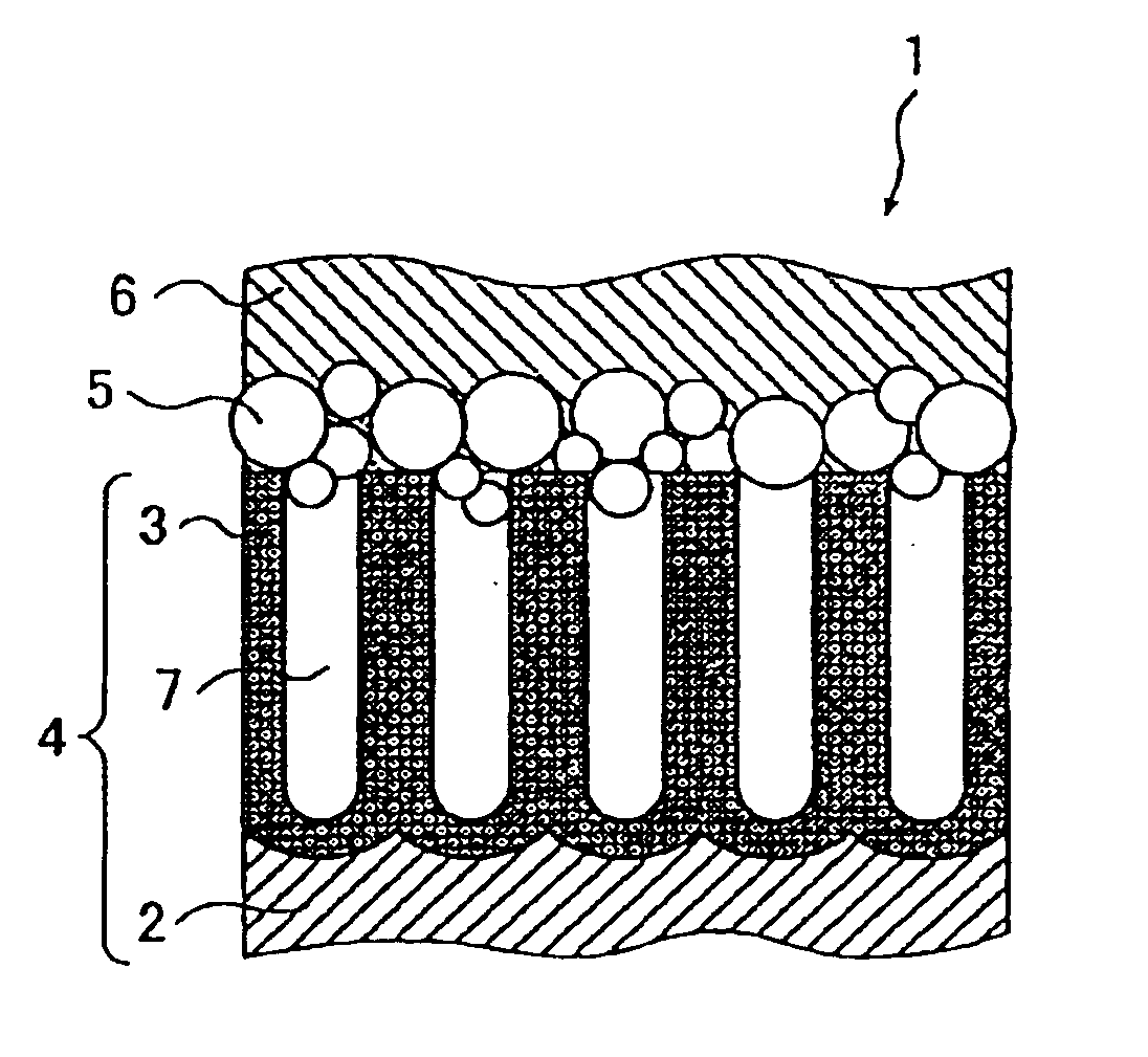
[0026]The present inventors have found, as the preferred first embodiment, that when the mouth diameter of the surface of the pores of the anodic oxide film on the metal support is from 0 to 30 nm and the maximum inside diameter is from 20 to 300 nm, residual color, residual film, smearing resistance (i.e., staining resistance) and press life of the lithographic printing plate precursor can be improved with maintaining sensitivity.
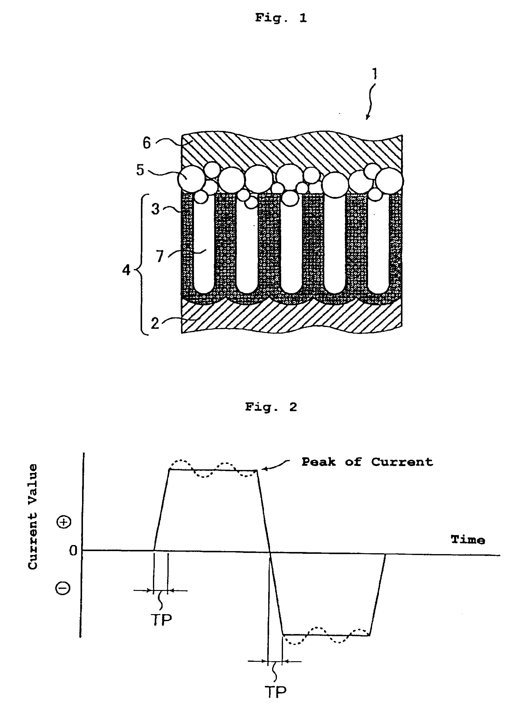
[0028]The present inventors have found, as the more preferred second embodiment, that by providing a specific particle layer between the anodic oxide film and the heat-sensitive layer in a thermal type lithographic printing plate precursor, a heat can be efficiently used in image-forming, and a lithographic printing plate precursor which is high insensitivity, excellent in press life and free of generation of smearing (i.e., staining) on a non-image area can be obtained.

Problems solved by technology

When aluminum is used as the support of these lithographic printing plate precursors for heat mode CTP (hereinafter simply referred to as “heat mode photographic material”), since the heat conductivity of aluminum is high, abrupt heat release to the support side occurs and exothermic loss is generated, which is one of the cause of the reduction of sensitivity.
On the other hand, techniques for higher sensitization by using organic materials having low heat conductivity, such as PET, as a support have been tried variously, but organic materials are low in hydrophilicity as compared with metallic materials and dimensional accuracy is deteriorated during printing by absorbing moisture, and so these materials cannot be used for printing of a high degree, e.g., color printing and highly precise printing in the present state.
However, when a film thickness is thickened, extra quantity of electricity of that portion is required, which causes the increase of production costs and, further, the pore is deepened by the increment of the thickness, and so the residual color is liable to be noticeable.
In addition, when pores are enlarged, adjacent pores form a multi-pore, which leads to extreme lowering of the anodic oxide film strength, and results in smearing due to peeling off of the film and also the deterioration of press life.
In the first place, in a positive type heat-sensitive layer, there is the problem of low sensitivity, i.e., when a heat diffuses to the inside of a support and an alkali solubilization reaction of the heat-sensitive layer becomes insufficient, a residual film is generated on the area to be a non-image area originally, and this is an essential problem of the positive type heat-sensitive layer.
Further, in such a thermal type positive lithographic printing plate precursor, infrared absorbers having a function of light / heat conversion is requisite, but these compounds are low in solubility due to comparatively large molecular weights, further they are adsorbed onto the micro pores formed by the anodic oxidation and it is difficult to removed them, and so there is another problem that a residual film is liable to be generated in a developing process by an alkali developing solution.
On the other hand, in a negative type heat-sensitive layer, when a heat diffuses to the inside of a support and the insolubilization in a developing solution of the heat-sensitive layer on the periphery of the interface of the heat-sensitive layer and the support becomes insufficient, an image is not formed sufficiently on the area to be an image area originally and the image is removed during development, or easily peeled off during printing, even if an image is formed.
However, in such a lithographic printing plate precursor, sensitivity is low due to the dissipation of heat to an aluminum support, and the strength of the image area of a heat-sensitive layer becomes weak when the coalescence of fine particles is insufficient, which causes an insufficient press life.
However, in the method of enlarging the micro pores of the anodic oxide film, the sensitivity and the press life are improved but the smearing resistance (i.e., also, called “the stain resistance”) is deteriorated.
On the other hand, in the method of sealing the micro pores, the smearing resistance is improved but the sensitivity and the press life are deteriorated.
Accordingly, sufficiently satisfactory level is not achieved yet in either case.

Method used


Image

  • Lithographic printing plate precursor
  • Lithographic printing plate precursor
  • Lithographic printing plate precursor

Examples


examples

[0363]The present invention is described in detail below with reference to the examples, but the present invention should not be construed as being limited thereto.

examples i-1 to i-6

and Comparative Examples I-1 to I-6

Thermal Positive Type Image-forming Layer Preparation of Support

[0364]As a metal substrate, an aluminum sheet having a thickness of 0.24 mm which had been surface-treated by an alkali degreasing method was used. The aluminum sheet was subjected to the following treatment in this order.

1) Mechanical Surface Roughening Treatment

[0365]The aluminum sheet was subjected to ablation with supplying an abrasive in a slurry state (pumice having an average particle size of about 15 μm) at a rotation number of 150 rpm with a No. 0.9 nylon brush.

2) Chemical Dissolution Treatment i

[0366]The concentration of sodium hydroxide was fixed at 20 wt %, the solution temperature was 40° C., and the treating time was adjusted so that Ra reached 0.3 μm. Thereafter, the aluminum sheet was washed with flowing water for 10 seconds, immersed in a solution having the concentration of sulfuric acid of 120 g / liter at solution temperature of 50° C. for 10 seconds, and desmutted. T...

examples i-7 to i-12

and Comparative Examples I-7 to I-12

Thermal Negative Type Image-forming Layer

[0388]The same procedures were repeated as in Examples I-1 to I-6 and Comparative Examples I-1 to I-6 up to sealing treatment, on the conditions as shown in Table I-2 below.

Formation of Image-forming Layer

[0389]The image-forming layer coating solution (prescription B) having the composition shown below was coated on a substrate by bar coating and the coated layer was dried in an oven at 100° C. for 1 minute. The thicknesses of the coating solution before and after coating were measured with a micrometer at 10 points and averaged. As a result, the average thickness of the thermal negative type image-forming layer (prescription B) was 1.5 μm on average and the standard deviation was 0.8 μm. The thickness computed from the weight variation of the coating solution before and after coating and specific gravity was 1.7 μm. This was used as the lithographic printing plate precursor.

[0390]

Image-forming layer coatin...


PUM

PropertyMeasurementUnit
Thicknessaaaaaaaaaa
Thicknessaaaaaaaaaa
Thicknessaaaaaaaaaa

Abstract

A lithographic printing plate precursor is disclosed, comprising a metal support having formed thereon an anodic oxide film, and an image-forming layer containing a light-to-heat converting agent, or a light-sensitive layer capable of image-forming with infrared laser exposure provided in this order from the support.

Description

FIELD OF THE INVENTION[0001]The present invention relates to a lithographic printing plate precursor, in particular, to a lithographic printing plate precursor which is capable of plate-making by scanning exposure based on digital signals, high sensitivity, free of residual color and residual film phenomena, and excellent in resistance to smearing (i.e., staining) and excellent in press life.[0002]Further, the present invention relates to a lithographic printing plate precursor capable of recording by an infrared laser, specifically to a lithographic printing plate precursor having a heat-sensitive layer capable of image-forming by exposure with an infrared laser.BACKGROUND OF THE INVENTION[0003]In the field of the lithographic printing plate precursor, metal supports are widely used. Above all, it is known that an oxide film can be formed when a direct electric current is turned on in an acid solution with an aluminum sheet as the anode, which is generally known as the Alumite trea...

Claims


Application Information

Patent Timeline
IPC IPC(8): B41N3/03
CPCB41N3/03C25F3/04B41N3/034Y10S430/145Y10S430/146
Inventor TOMITA, TADABUMIMATSUURA, ATSUSHIUESUGI, AKIOTERAOKA, KATSUYUKIHOTTA, HISASHI
Owner FUJIFILM CORP
Why Eureka
Eureka Blog
Learn More