Method and apparatus for fabrication of plastic fiber optic block materials and large flat panel displays

a technology of plastic fiber optic blocks and flat panel displays, which is applied in the direction of instruments, other domestic objects, optical elements, etc., can solve the problems of inefficient and complicated way of achieving the inability to efficiently utilize the method of making optical arrays or matrices with very fine cores, and the serious deterioration of the effect of cladding achieved in this way, etc., to achieve good light transmission, easy connection, and high resolution

Inactive Publication Date: 2005-05-10
FLORIDA UNIV OF A FLORIDA
View PDF40 Cites 25 Cited by
  • Summary
  • Abstract
  • Description
  • Claims
  • Application Information

AI Technical Summary

Benefits of technology

[0021]The present invention pertains to the manufacturing of plastic optical fiber sheets comprising a plurality of polymer optical fibers in the form of a one dimensional array. The optical fiber sheet, or ribbon, can be used for transmitting multi-channel optical signals and can offer the advantage of easy connection. In addition, the sheets

Problems solved by technology

A disadvantage of this method is its complicated and inefficient way of achieving the effect of cladding.
In addition, this method cannot be efficiently utilized for making optical arrays or matrices with very fine cores.
The effective cladding achieved in this way can be seriously deteriorated in the drawing process.
Limited production rate due to difficulty in cooling a symmetric matrix of optical fibers is a significant limitation of the Mitsubishi patents.
Another limitation of the Mitsubishi patents is the use of step-index optical fiber which can reduce the light transmission at small microfiber diameters.
The difference in loss for different colors can lead to image color distortion.
As a result of these considerations, existing image guides using step-index plastic optical fibers compromise both the optical transmission and the fidelity of image color.
The use of this method is limited by the polymers which can be used.
However, because this production method involves stacking, fusing, and drawing a plurality of single fibers, a practical limitation of

Method used


Image

  • Method and apparatus for fabrication of plastic fiber optic block materials and large flat panel displays
  • Method and apparatus for fabrication of plastic fiber optic block materials and large flat panel displays
  • Method and apparatus for fabrication of plastic fiber optic block materials and large flat panel displays

Examples


example 1

Production of Massive Fiber Optic Plate with Fibers Parallel to the Normal to the Plate Surface

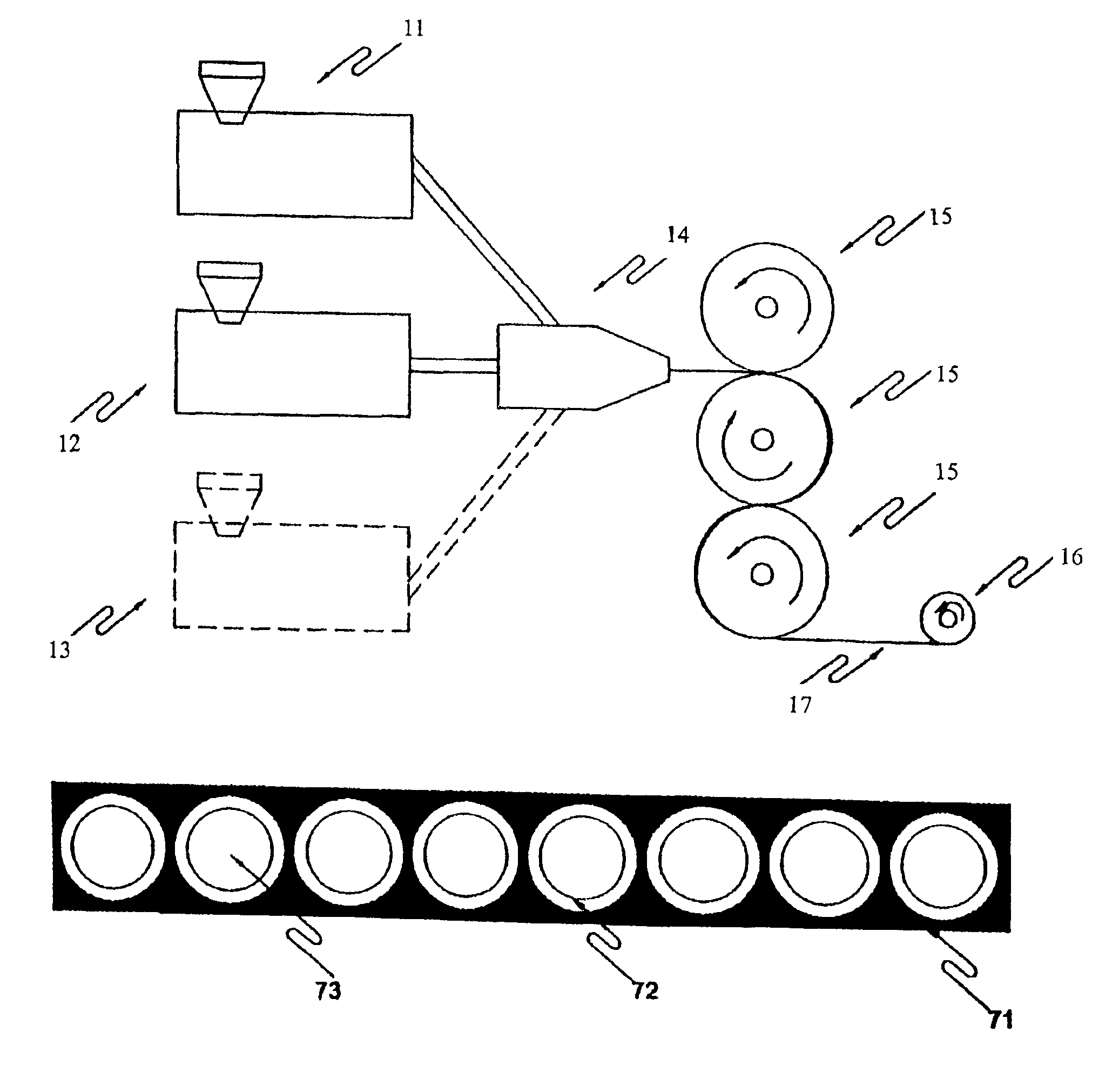
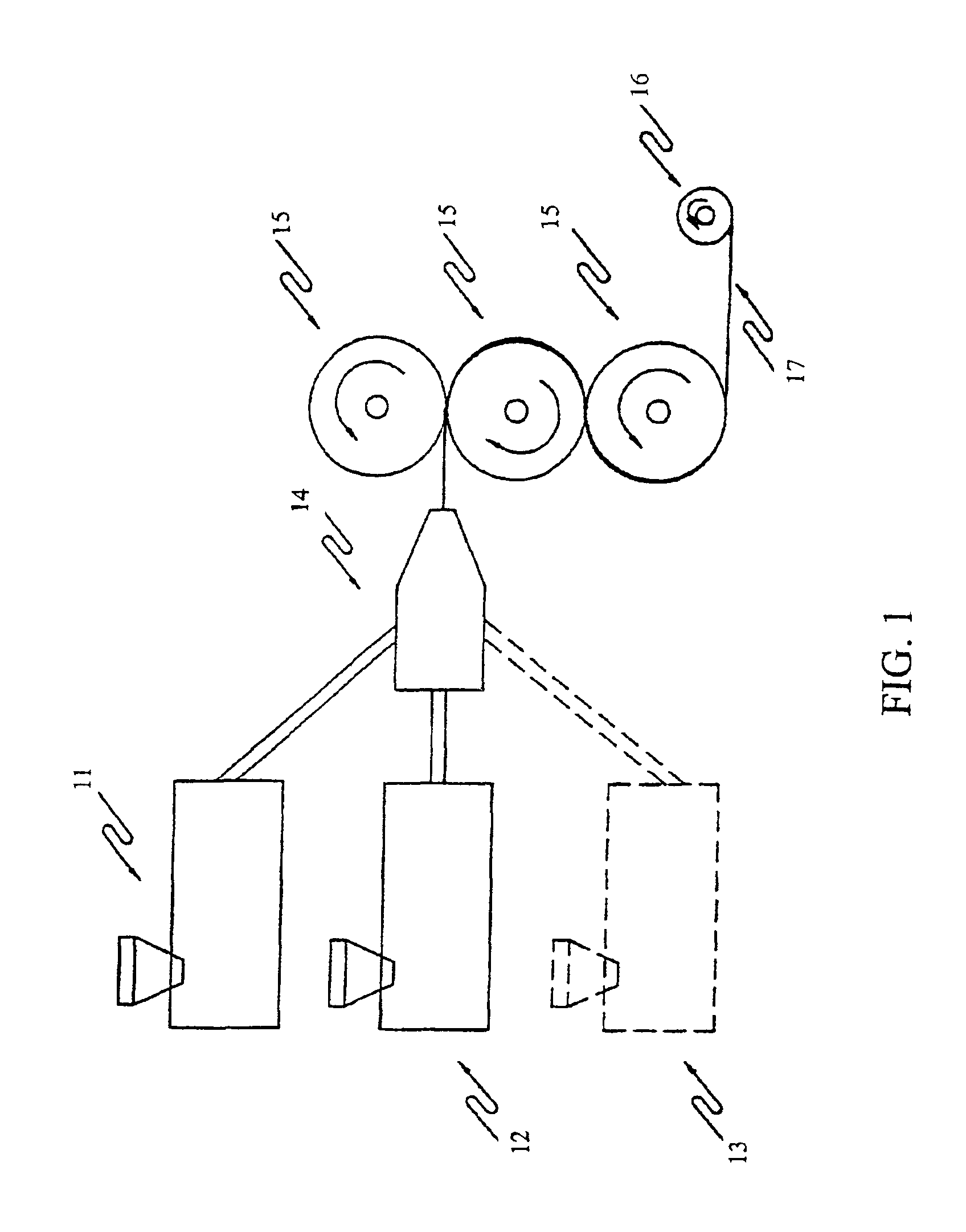
[0149]Polystyrene containing 3% by weight of diphenyl sulphide was selected as the core material. Polymethylmethacrylate with 3% by weight of Tributyl phosphate was selected as the cladding material. Polymethylmethacrylate containing 5% by weight of carbon black in the form of particles whose average size was less than 0.2 microns was selected as the sea material.

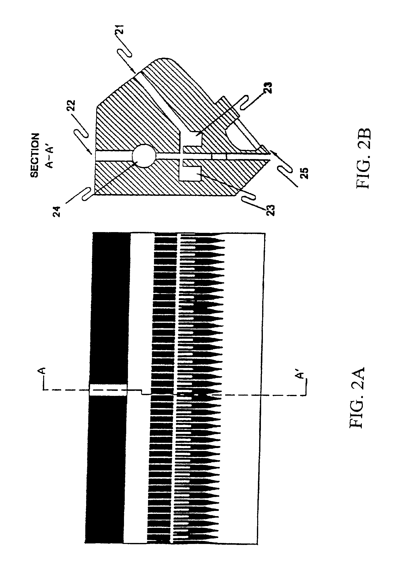
[0150]The above materials were extruded through a die similar to that shown in FIG. 6, having an exit slit 50 cm wide. The fiber center-to-center spacing in the drawn sheet was 25 μm and the die was designed to produce four rows of fibers with a final sheet thickness of about 100 μm. The structure of the core holes in the die was an oval with major and minor axes of 200 μm and 27 μm respectively. The total fiber array was 4×20,000 and a schematic of a short section of this type of ribbon is shown in FIG. 7C. The temperature of the...

example 2

Continuous, High-Speed Production of Massive Fiberoptic Plate Using Adhesive Between Sheets

[0154]Sheet was produced using the materials given in Example 1. The fiber center-to-center spacing in the drawn sheet was 100 microns and there were four rows of fibers with a final sheet thickness of about 400 microns. The width of the cut sheet was 46.0 cm as in Example 1. Sheet was produced at the rate of 20 meters per minute.

[0155]The winding fixture shown schematically in FIGS. 12 and 13 was four meters in length. Winding of the sheet was begun. When the first layer of sheet on one side of the fixture was laid, a spray of adhesive was made to cover the surface of the sheet. As the fixture rotated, a second sheet layer was laid on top of the adhesive. As the second sheet came into contact with the adhesive, a roller pressed the second sheet into intimate contact with the adhesive and, thereby, the first sheet. The adhesive used was DARC CURER® manufactured by Dymax, Torrington, Conn. Imme...

example 3

Production of Massive Fiber Optic Plate with Fibers Parallel to the Plate Surface

[0159]It is desired to produce a plate 114 cm×85 cm×8.5 cm thick with fibers beginning and ending on the sides whose areas are 114×8.5 cm2.

[0160]Core material was chosen to be polystyrene. The cladding material was polymethylmethacrylate with 3% by weight of methyl perfluorooctanate. In this case, sea material was not employed. A 120 cm wide die similar to that shown in FIG. 2 was used with four rows of core holes, each hole having dimensions 32 μm×300 μm.

[0161]Extrusion was carried out as in Example 1 and the extruded sheet was cut to produce a final width of 113.9 cm and the fiber cores were approximately circular and about 30 μm diameter and had axis-to-axis distance of 34 μm. The fiber array in the final sheet was 4×33,500.

[0162]The 136 μm thick sheet was wound on to a pair of 114 cm wide rotating fixtures, the length of which were 175 cm as shown schematically in FIGS. 12 and 13. A total of 625 lay...


PUM

PropertyMeasurementUnit
Lengthaaaaaaaaaa
Diameteraaaaaaaaaa
Diameteraaaaaaaaaa

Abstract

This invention concerns a method and apparatus for manufacturing a sheet and a two-dimensional matrix of plastic optical fibers. The fibers may be of the step-index or graded-index type. Co-extrusion through a specially designed die is used to produce a sheet composed of a fiber array. The fiber sheet (ribbon) can be used for transmitting optical signals. These arrays may also be stacked and fused at high temperatures to form the two-dimensional matrix required for many applications such as large area image transfer. In addition, a high-speed, continuous manufacturing method is disclosed to produce a massive two-dimensional matrix of fibers. The method of manufacture permits high quality image transfer at low manufacturing cost in a wide array of geometries.

Description

CROSS-REFERENCE TO A RELATED APPLICATION[0001]This application claims priority from provisional patent application U.S. Ser. No. 60 / 267,885, filed Feb. 9, 2001 and provisional patent application 60 / 255,553, filed Dec. 14, 2000.BACKGROUND OF THE INVENTION[0002]Optical fibers are well known in the art of light transmission along a length of filament by multiple internal reflection of light. A single-core optical fiber usually consists of a core and a cladding which has an index of refraction lower than that of the core. A multi optical fiber bundle, often referred to as an image guide, can be effectively considered as a bundle of single optical fibers where each fiber transmits a light signal independent of the others. Optical fibers may be fabricated from glass or plastic.[0003]One of the largest applications of a two-dimensional image guide is for transferring images. Because each individual fiber of the optical image guide transmits only a minute discrete portion of the image, it i...

Claims


Application Information

Patent Timeline
IPC IPC(8): B29C47/06B29C69/02B29C47/02D01D5/34G02B6/06G02B6/08G02B6/25B29C48/08B29D11/00
CPCG02B6/25B29C47/0038B29C47/0047B29C47/027B29C47/065B29C47/145B29D11/00663D01D5/34G02B6/06G02B6/08B29C47/0014B29C47/0021B29C47/0057B29K2025/00B29K2033/12B29K2069/00B29K2105/0085B29L2007/008B29L2011/0075B29C47/0019B29C48/05B29C48/07B29C48/08B29C48/001B29C48/0014B29C48/0018B29C48/156B29C48/21B29C48/307
Inventor WALKER, JAMES K.TYMIANSKI, JACOB R.LI, YONGCHENGLEE, BONGSOOCOUCH, JONATHAN
Owner FLORIDA UNIV OF A FLORIDA
Why Eureka
Try Eureka