
Arrangement for generating extreme ultraviolet (EUV) radiation based on a gas discharge

a technology of ultraviolet radiation and gas discharge, which is applied in the direction of optical radiation measurement, gas-filled discharge tubes, x-ray tubes, etc., can solve the problems of limited number of apertures, reduced system resolution, and restricted diversity of optical elements, and achieves stable generation

Inactive Publication Date: 2005-05-17
USHIO DENKI KK
View PDF17 Cites 80 Cited by
  • Summary
  • Abstract
  • Description
  • Claims
  • Application Information

AI Technical Summary

Benefits of technology

The invention provides a new way to generate extreme ultraviolet (EUV) radiation by using a gas discharge with a coaxially arranged preionization unit. The preionization unit has flat electrodes and a cylindrical insulator with channels for a coolant. The insulator is extended into the first electrode housing to ensure reliable insulation. The tubular insulator in the second electrode housing covers the cylindrical surfaces of the second electrode housing. The invention allows for a stable generation of a dense, hot plasma column and achieves a high repetition frequency and high temperature. The electrode housings are made from materials with high proportions of tungsten, tantalum, or molybdenum to withstand the high current load and thermal stress.

Problems solved by technology

However, the optical systems must comprise reflection optics at wavelengths below 157 nm because there are no available materials which are transparent for these wavelengths.
When using reflection optics, the numerical aperture is limited and the diversity of optical elements is restricted.
The lower numerical aperture of the optics results in decreased resolution of the system which can only be compensated by an even shorter wavelength (by about an order of magnitude).
This twofold conversion results in reduced conversion efficiency compared to gas discharge.
Compared to the other concepts, the plasma focus method has the disadvantage of poor spatial stability because of the formation of plasma.
However, this leads to additional contamination of the surroundings, particularly the insulator.
Another competing concept, capillary discharge, has only a short life and, consequently, limited applicability.
This high-frequency preionization system is directly coupled to the discharge system and is therefore exposed to plasma radiation and to bombardment by charged particles resulting in a shorter life of the insulator tube in particular.

Method used


Image

  • Arrangement for generating extreme ultraviolet (EUV) radiation based on a gas discharge
  • Arrangement for generating extreme ultraviolet (EUV) radiation based on a gas discharge
  • Arrangement for generating extreme ultraviolet (EUV) radiation based on a gas discharge

Examples


Embodiment Construction

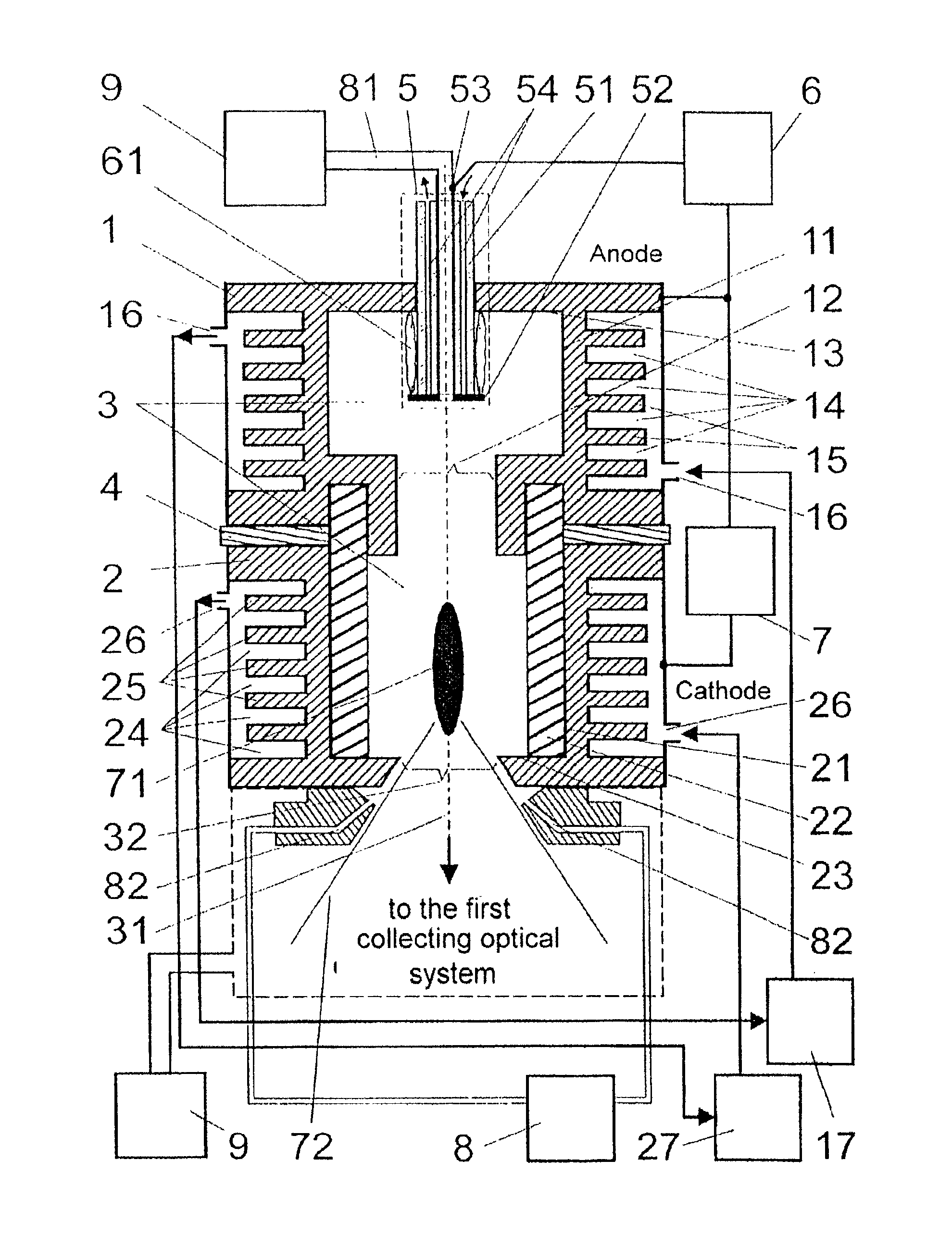
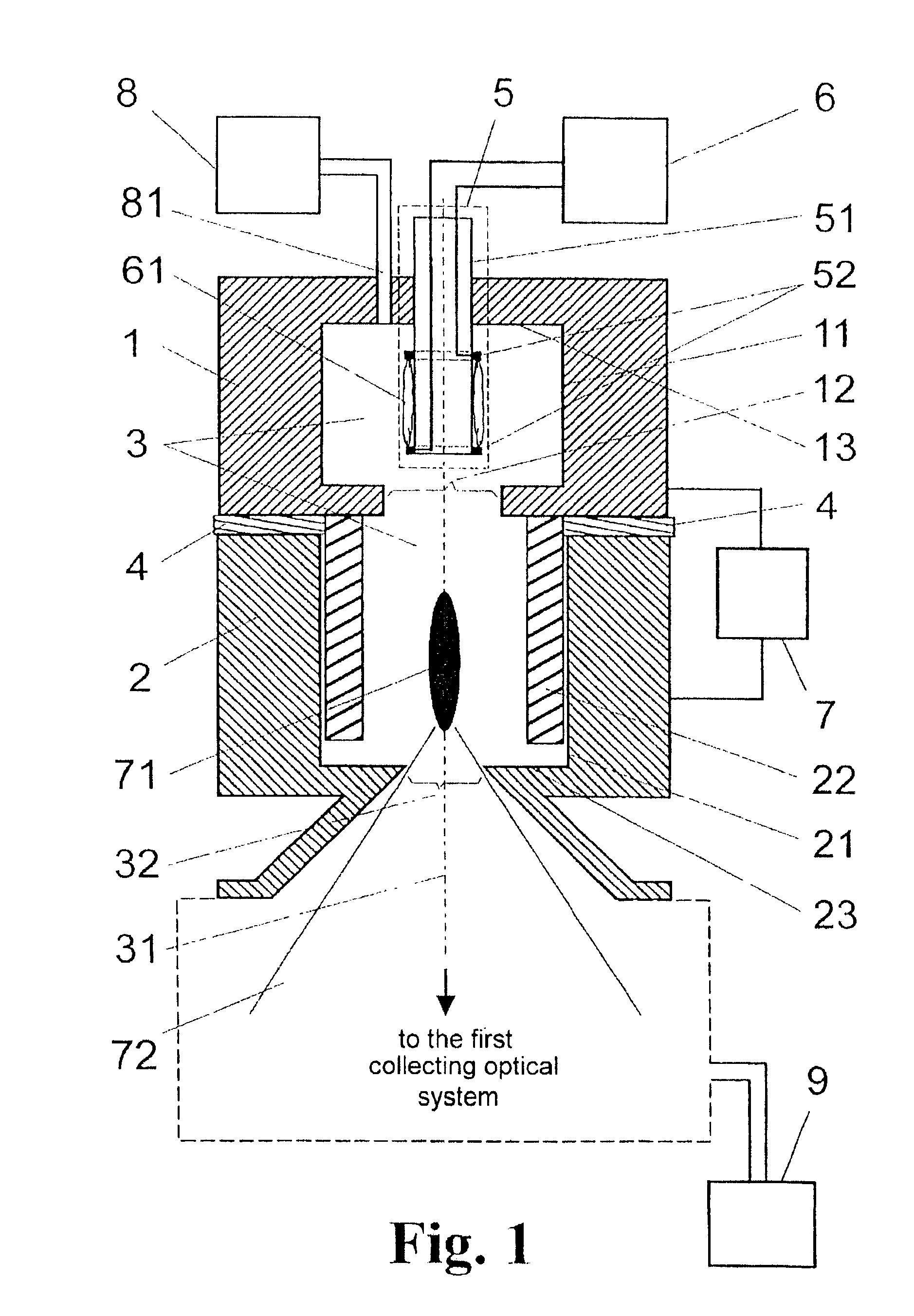
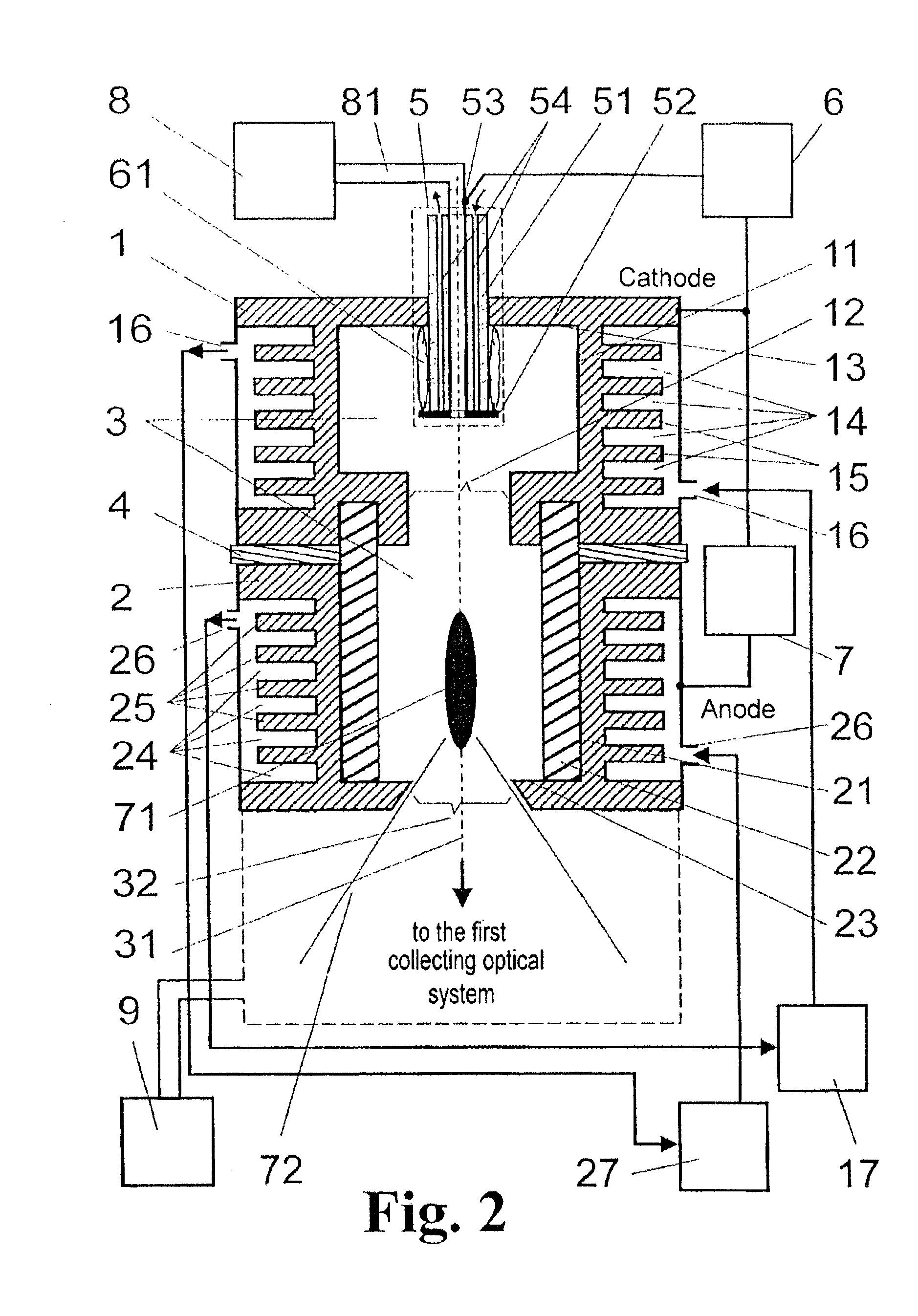
[0037]As is shown in FIG. 1, the basic arrangement according to the invention comprises a first electrode housing 1 and a second electrode housing 2 which together form a discharge chamber 3, the two electrode housings 1 and 2 being insulated relative to one another against breakthrough by an insulating layer 4 and a tubular insulator 22 in the interior of the second electrode housing 2, a preionization unit 5 which is arranged coaxially inside the first electrode housing 1 and communicates with the preionization pulse generator 6, a high-voltage pulse generator 7 to which the two electrode housings 1 and 2 are connected, a gas supply system 8 for feeding working gas into the discharge chamber 3 so as to be regulated in a defined manner, and a vacuum system 9.

[0038]The two electrode housings 1 and 2 are arranged coaxially one over the other and have inner cylinder superficies surfaces 11 and 21 which define the discharge chamber 3 radially around the axis of symmetry 31. The first e...


PUM

PropertyMeasurementUnit
frequencyaaaaaaaaaa
frequencyaaaaaaaaaa
wavelength rangeaaaaaaaaaa

Abstract

The invention is directed to a method and an arrangement for generating extreme ultraviolet (EUV) radiation, i.e., radiation of high-energy photons in the wavelength range from 11 to 14 nm, based on a gas discharge. The object of the invention, to find a novel possibility for generating EUV radiation in which an extended life of the system is achieved with stable generation of a dense, hot plasma column, is met according to the invention in that a preionization discharge is ignited between two parallel disk-shaped flat electrodes prior to the main discharge by a surface discharge along the superficies surface of a cylindrical insulator with a plasma column generated through the gas discharge with pulsed direct voltage, which preionization discharge carries out an ionization of the working gas in the discharge chamber by means of fast charged particles. The preionization discharge is triggered within a first electrode housing and the main discharge takes place between a narrowed output of the first electrode housing and a part of the second electrode housing close to the outlet opening of the discharge chamber. The plasma develops in a part of the second electrode housing covered by a tubular insulator and, as a result of the current-induced magnetic field, contracts to form a dense, hot plasma column, one end of which is located in the vicinity of the outlet opening of the second electrode housing.

Description

CROSS-REFERENCE TO RELATED APPLICATIONS[0001]This application claims priority of German Application No. 101 51 080.2, filed Oct. 10, 2001, the complete disclosure of which is hereby incorporated by reference.BACKGROUND OF THE INVENTION[0002]a) Field of the Invention[0003]The invention is directed to an arrangement for generating extreme ultraviolet (EUV) radiation based on a gas discharge, i.e., radiation of high-energy photons in the wavelength range from 11 to 14 nm (EUV=extreme ultraviolet range).[0004]b) Description of the Related Art[0005]As structures of integrated circuits on chips become increasingly smaller in the future, radiation of increasingly shorter wavelength will be needed in the semiconductor industry to expose these structures. Lithography machines with excimer lasers which attain their shortest wavelength at 157 nm and in which transmission optics or catadioptic systems are employed are currently in use.[0006]Therefore, radiation sources which further increase re...

Claims


Application Information

Patent Timeline
Patent Type & Authority Patents(United States)
IPC IPC(8): G03F7/20H05G2/00G21K5/00G21K5/02H01L21/027H05H1/24
CPCG03F7/70033H05G2/005H05G2/003
Inventor AHMAD, IMTIAZSCHRIEVER, GUIDOKLEINSCHMIDT, JUERGEN
Owner USHIO DENKI KK
Learn More