Digital image projector with oriented fixed-polarization-axis polarizing beamsplitter

a fixed-polarization axis, beam splitting technology, applied in the field of digital image projectors, can solve the problems of insufficient reduction of light leakage to dark-pixel locations in the projected image, conventional digital image projectors based on reflective polarization modulators, and failure to completely achieve the effect of reducing the amount of light leakage to dark-pixel locations

Inactive Publication Date: 2005-05-24
KONINKLIJKE PHILIPS ELECTRONICS NV
View PDF15 Cites 23 Cited by
  • Summary
  • Abstract
  • Description
  • Claims
  • Application Information

AI Technical Summary

Benefits of technology

[0067]An alternative preferred plate-supported, surface-mounted fixed-polarization-axis thin-polarizer polarizing beamsplitter for the digital-image projector of the invention is a plate-supported, surface-mounted alternating birefingent / nonbirefringent-film-polarizer polarizing beamsplitter. The plate-supported, surface-mounted alternating birefringent / nonbirefringent-film-polarizer polarizing beamsplitter comprises a transparent film-support plate and an alternating birefringent / nonbirefringent-film polarizer mounted on an outer film-support face of the film-support plate. The alternating birefringent / nonbirefringent-film polarizer includes alternating layers of oriented birefringent material and nonbirefringent material in which the index of refraction of the nonbirefringent material substantially equals one of the indices of refraction of the oriented birefringent material. Since the indices of refraction of the alternating layers of material are matched in one direction and not matched in the orthogonal direction, light of one polarization direction effectively “sees” a uniform index of refraction and is transmitted through the multilayer film, whereas light of the orthogonal polarization sees a stack of layers of alternating, differing indices of refraction and is reflected. Such an alternating birefringent / nonbirefringent-film polarizer is described in published international PCT patent application No. WO 00 / 70386. A multilayer stack of alternating birefringent / nonbirefringent-film could be disposed on an outer film-support face of a transparent film-support plate which could be oriented at, for example, 45° to the axis of an incident beam to form a polarizing beamsplitter. The polarization axes are determined by the orientation of the birefringent layers. Thus, like the wire-grid polarizing beamsplitter, such a polarizing beamsplitter tends to avoid the skew angle problem of conventional MacNeille-type multilayer dielectric film polarizing beamsplitters.

Problems solved by technology

A difficulty with conventional digital-image projectors that are based on reflective polarization modulators arises because a conventional MacNeille-type multilayer 
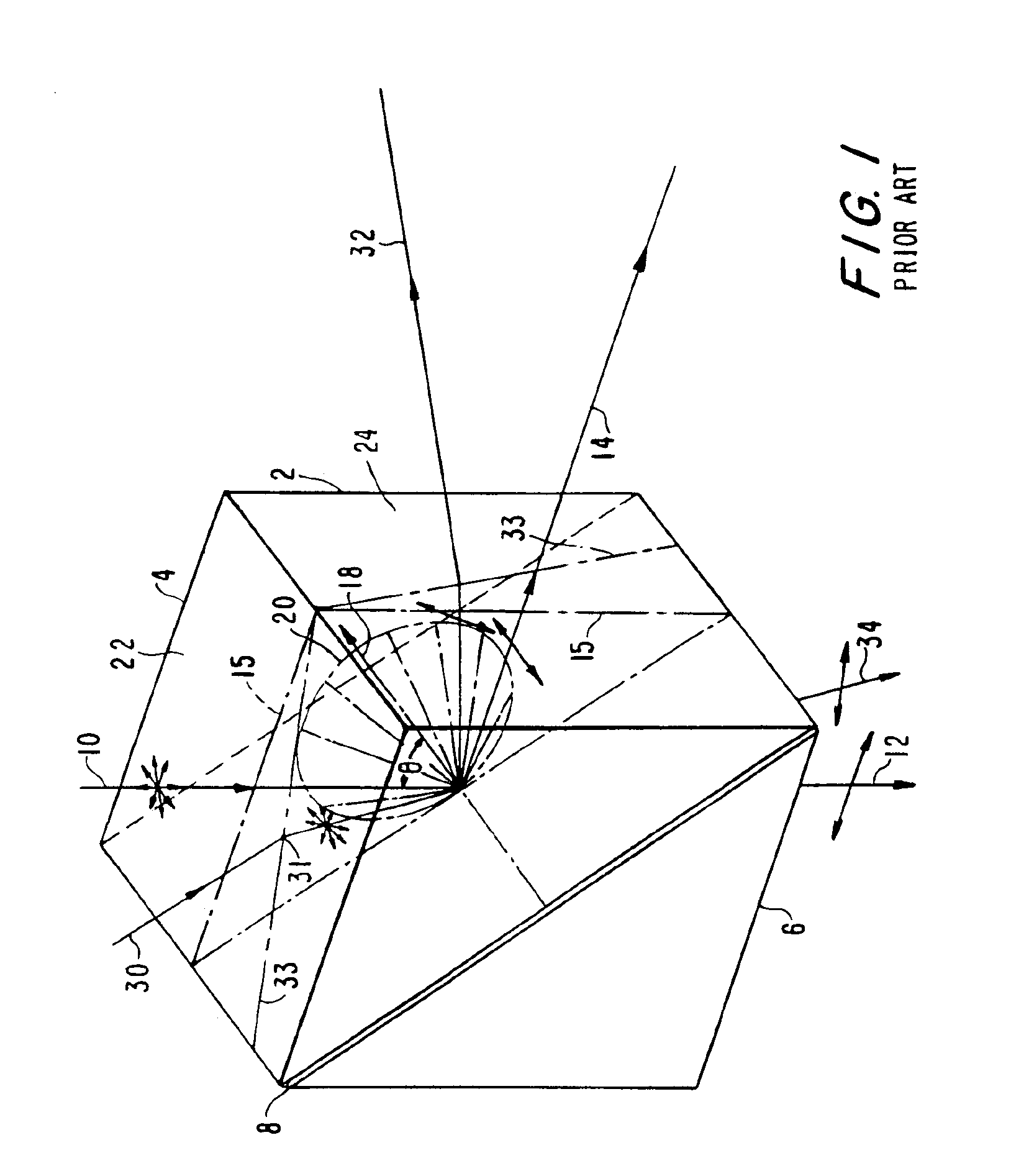
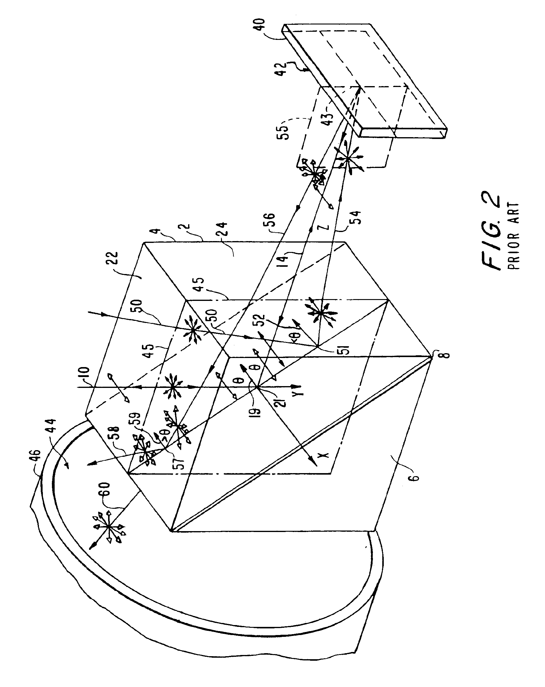
dielectric film polarizing beamsplitter of the type heretofore typically used in such projectors generally treats two light rays impinging upon the polarizing beamsplitter differently with respect to polarization properties if the directions of incidence of the two rays differ with respect to the polarizing beamsplitter.
As a consequence of the dependency of the polarizing properties of such a beamsplitter on the direction of an incident ray and the ray discrimination properties of such a beamsplitter on both the polarization state of an incident ray and the direction of incidence of the ray, conventional digital image projectors have had difficulties in reducing to a sufficient degree the amount of light leaking to dark-pixel locations in a projected image.
However, as discussed below, such attempts have not been completely successful and entail additional drawbacks.
However, use of such polarizing films entails additional expense in manufacturing a digital-image projector and additional loss of illumination intensity in the operation of the digital-image projector.
Moreover, such polarizing films would not eliminate entirely the problem of leakage from off-angle rays and on-angle, off-axis rays discussed in the preceding paragraphs in connection with FIGS. 2 and 3.
Although use of such quarter-wave foils can enhance the light-to-dark contrast ratio of digital-image projectors to a degree, the correction is never perfect.
Moreover, there are a number of practical disadvantages to such use of quarter-wave foils.
First, quarter-wave foils constitute additional components which must be included in the system and represent an increase in manufacturing and parts costs.
Mounting the foil is difficult, since orientation of the foil must be precise.
Lamination of the foil to a support can bring difficulties, such as cosmetic problems of dust and other flaws in the lamination that appear as bright spots in a dark field.
If the foil is laminated to the polarizing beamsplitter or polarization modulator face, any errors can result in manufacturing yield loss or additional cost in rework.
Fresnel reflections from the foil can therefore not be fully eliminated and could limit contrast in future very high contrast systems.
Finally, the quarter-wave foil must act as a quarter-wave retarder over the entire wavelength region of interest, which is difficult to achieve.
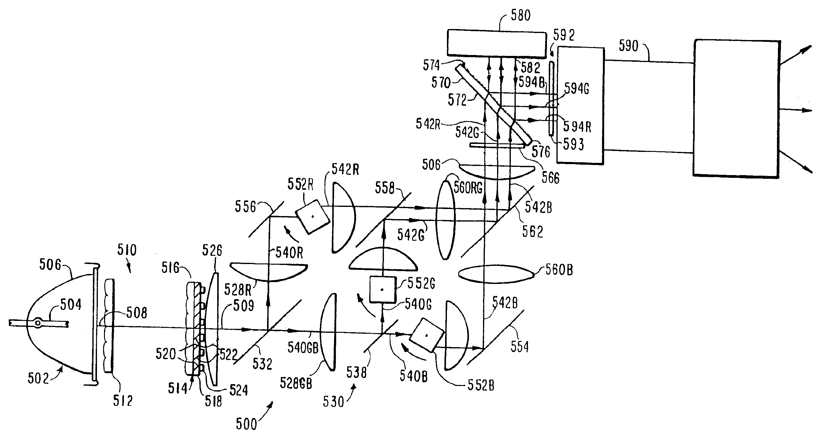
An additional problem can arise in a digital-image projector which employs a conventional MacNeille-type polarizing beamsplitter which has a multilayer dielectric polarizing film positioned on a hypotenuse face between two prisms.
As even small amounts of light are absorbed in the prisms or in the polarizing film, the bulk of the glass of the prisms of the beamsplitter can experience stress.
Such stress-induced polarization change can result in unacceptable light leakage in the dark state.
However, such glass tends to be expensive.
A multilayer dielectric film based plate-beamsplitter is not possible in air.
Although a liquid-immersed polarizing beamsplitter can be made with a high-index-of-refraction liquid medium, such beamsplitters tend to have practical difficulties with respect to maintaining the purity of the liquid and avoiding temperature gradients within the liquid.
However, as a practical matter, dark-state leakage from modulator reflected off-axis rays from around the pupil of an illumination beam in the case of high-performance wire-grid polarizing beamsplitters is significantly less of a problem than in the case of conventional MacNeille-type multilayer dielectric film beamsplitters.
Wire-grid-polarizer polarizing beamsplitters in configurations heretofore disclosed for digital image projection systems can have drawbacks, particularly for high-resolution image projection systems.
However, a thick plate of optical glass can suffer from stress birefringence, either from thermal effects or externally applied stress.
In configurations heretofore disclosed for digital image projection systems such as illustrated in FIGS. 4 and 5 above, beams bearing images to be projected have been required to pass through the grid-support plate of the wire-grid-polarizer polarizing beamsplitter and consequently such beams have been at risk for image distortion caused by stress birefringence in the grid-support plate.
In addition, the thick grid-support plate of a wire-grid polarizer when tilted as required for use as a polarizing beamsplitter can introduce astigmatism, and to a lesser extent coma, into a beam passing at the tilted angle through the grid-support plate, giving rise to risk of further distortion of images born by a beam passing through a tilted grid support plate in digital-image projection-system configurations heretofore disclosed.
As noted above, a thick glass plate can suffer from stress birefringence.
However, because of the orientation of the polarizing beamsplitter 100 with grid-support plate 104 of the polarizing beamsplitter 100 facing an illumination-source side of the optical system of the projector, such stress birefringence will essentially affect only the illumination beam 170 and result in a negligible loss in efficiency.
However, such aberrations for the beamsplitter orientation of FIG. 6 are in the illumination path.

Method used


Image

  • Digital image projector with oriented fixed-polarization-axis polarizing beamsplitter
  • Digital image projector with oriented fixed-polarization-axis polarizing beamsplitter
  • Digital image projector with oriented fixed-polarization-axis polarizing beamsplitter

Examples


Embodiment Construction

[0080]Turning now FIG. 7, a first preferred digital-image projector 500 includes an illumination-beam source assembly 502, which includes a high-intensity lamp 504 located in a parabolic reflector 506. The illumination-beam source assembly 502 produces an illumination beam of unpolarized, white-spectrum light for the projector. For simplicity, in FIG. 7 beams of light are indicated only by the central rays of the various beams, such as the central ray 508 of the unpolarized illumination beam produced by the illumination-beam source assembly 502. Ultraviolet, infrared, and color-compensation filters (not shown) are placed in the path of the illumination beam to remove light of ultraviolet and infrared frequencies from the beam and impart a desired color spectral shape to the frequency spectrum of the beam.

[0081]A light-conserving beam-polarizer assembly 510 is located in the path of the unpolarized illumination beam 508 in the preferred digital-image projector 500. The beam-polarizer...


PUM

PropertyMeasurementUnit
angleaaaaaaaaaa
polarizing angleaaaaaaaaaa
wavelengthaaaaaaaaaa

Abstract

A digital image projector includes an illumination-light source lamp and illumination beam forming optics for forming a white-spectrum illumination beam and color-band-separation optics to divide the illumination beam into color-component subbeams. The digital image projector also includes a reflective digital-image-encoding polarization modulator mechanism such as a reflective liquid crystal display polarization modulator to reflectively modulate the linearly polarized subbeams to form color-component image encoded-polarization subbeams and projection lens optics for projecting a color image divided from the image encoded-polarization subbeams. The digital image projector further includes a plate-supported, surface mounted fixed polarization-axis polarizing beamsplitter such as a wire-grid polarizing beamsplitter for dividing the color image from the image-encoded-polarization subbeams in which a polarizer support plate of the polarizing beamsplitter faces an illumination-source side of the optical system of the projector.

Description

CROSS-REFERENCES TO RELATED APPLICATION(S)[0001]This application is a continuation of U.S. patent application Ser. No. 09 / 873,883, “DIGITAL IMAGE PROJECTOR WITH ORIENTED FIXED-POLARIZATION-AXIS POLARIZING BEAMSPLITTER”, filed on Jun. 2, 2001 in the names of Jeffrey A. Shimizu, Peter J. M. Janssen, and Stephen MeClain, now issued as U.S. Pat. No. 6,511,183.FIELD OF TECHNOLOGY[0002]The present invention broadly concerns digital image projectors and more particularly concerns digital image projectors based on reflective digital-image polarization modulators such as reflective liquid-crystal display polarization modulators.BACKGROUND AND SUMMARY[0003]Digital image projectors are widely used to project color images generated from digital signals encoding the images onto the front of a reflective display screen for a conference-room presentation or the like or onto the rear of a semi-transparent diffusive screen of a rear-projection display monitor or a projection television.[0004]A conve...

Claims


Application Information

Patent Timeline
Patent Type & Authority Patents(United States)
IPC IPC(8): G02B27/28H04N9/31H04N5/74G02F1/13G02F1/1335G03B21/00
CPCG02B27/283H04N9/3197H04N9/3117H04N5/7441G03B21/14
Inventor SHIMIZU, JEFFREY A.JANSSEN, PETER J. M.MCCLAIN, STEPHEN
Owner KONINKLIJKE PHILIPS ELECTRONICS NV
Why Eureka
Try Eureka