Method of forming a resist pattern and fabricating tapered features

a technology of resist pattern and tapered feature, which is applied in the direction of photomechanical equipment, instruments, photosensitive material processing, etc., can solve the problems of difficult control of taper angle and incomplete formation of holes, and achieve accurate control and high reliability

Inactive Publication Date: 2005-05-31
LAPIS SEMICON CO LTD
View PDF8 Cites 4 Cited by
  • Summary
  • Abstract
  • Description
  • Claims
  • Application Information

AI Technical Summary

Benefits of technology

[0007]An object of the present invention is to form holes and other features with accurately controllable taper during the fabrication of a microelectronic device.
[0011]The dimensions of the tapered features created in the substrate are accurately controllable by control of the energy beam dosage and other parameters in the formation of the tapered resist pattern. Tapered features can therefore be formed with high reliability.

Problems solved by technology

In the tapered etching technology described above, however, it is difficult to control the taper angle, and etching may stop due to the deposition of material, leaving holes incompletely formed.

Method used


Image

  • Method of forming a resist pattern and fabricating tapered features
  • Method of forming a resist pattern and fabricating tapered features
  • Method of forming a resist pattern and fabricating tapered features

Examples


first embodiment

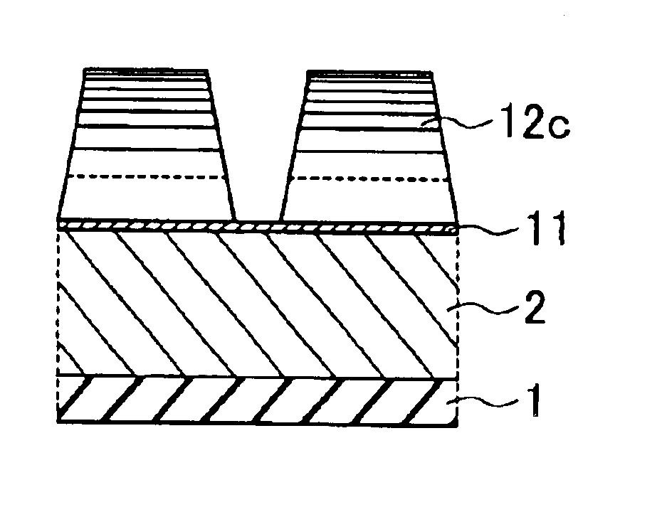
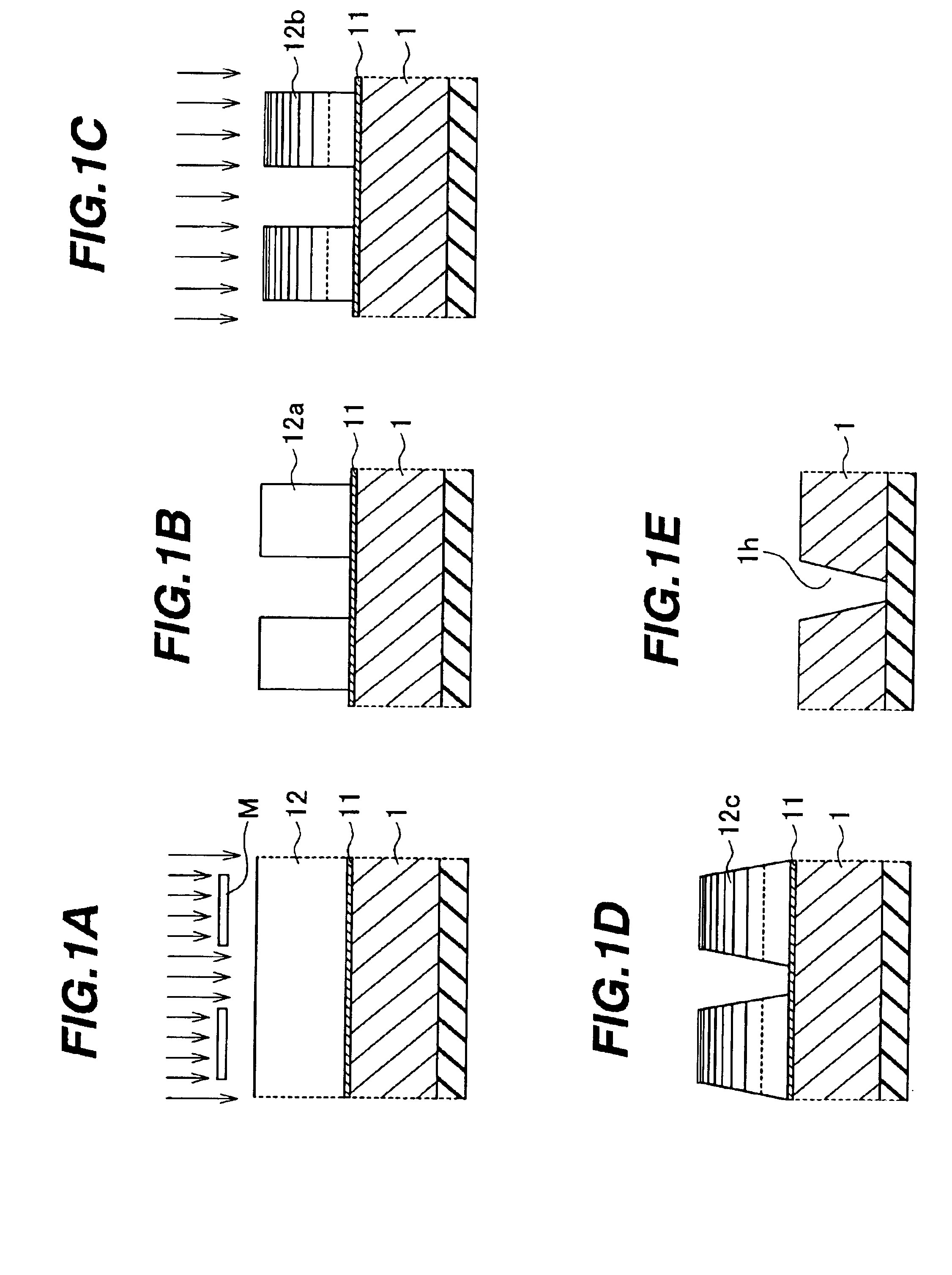
[0016](Step 1) As shown in FIG. 1A, the surface of a semiconductor substrate such as a silicon (Si) wafer substrate 1 is given an antireflection coating 11 approximately 110 nm thick, then coated with a photoresist 12 having a glass transition temperature that increases under irradiation by an electron beam. An example of a suitable photoresist is the SEPR411 chemically amplified positive photoresist made by Shin-Etsu Chemical Co., Ltd. The photoresist coating is approximately 1000 nm thick. The substrate and its coatings are baked at a temperature of about 100 degrees Celsius; then a krypton fluoride (KrF) excimer laser exposure system (numerical aperture=0.60, σ=0.75) is used to expose the photoresist 12 to approximately 95 mJ / cm2 of ultraviolet light through a mask M having a desired circuit design pattern, including hole patterns 0.28 μm in diameter.

[0017](Step 2) After the exposure, the photoresist 12 is developed in a 2.38 percent (%) tetramethyl ammonium hydroxide (TMAH) deve...

second embodiment

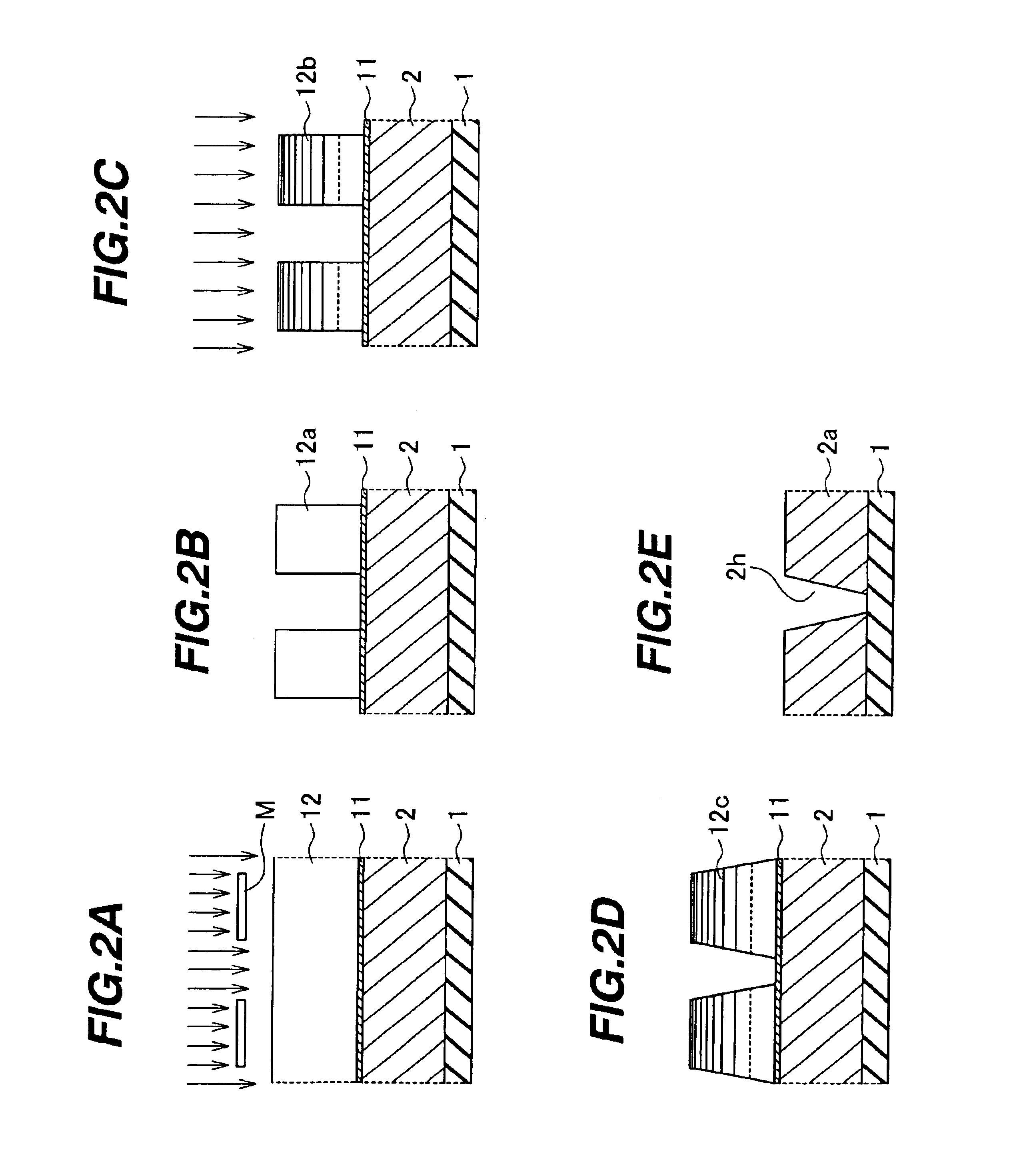
[0022](Step 1) A silicon substrate 1 is processed to form isolation regions and gate electrodes (not shown); then an interlayer dielectric film 2 such as a silicon oxide film (nondoped silicate glass, NSG) approximately 1000 nm thick is formed on the surface of the silicon substrate 1. The word ‘substrate’ will be used below to refer to both the silicon substrate 1 and the interlayer dielectric film 2. The substrate surface is coated with an antireflection coating 11 with a thickness of approximately 110 nm; then a photoresist 12 having a glass transition temperature that increases under irradiation by an electron beam is coated onto the antireflection coating 11 to a thickness of approximately 1000 nm, and baked at a temperature of about 100 degrees Celsius.

[0023]Next, as shown in FIG. 2A, the photoresist 12 is exposed to ultraviolet light at approximately 95 mJ / cm2 by a KrF excimer laser exposure system (numerical aperture=0.60, σ=0.75), through a mask M having a desired circuit d...


PUM

PropertyMeasurementUnit
diameteraaaaaaaaaa
diameteraaaaaaaaaa
thickaaaaaaaaaa

Abstract

A resist pattern for fabricating a microelectronic device is irradiated with an energy beam, raising the glass transition temperature of the upper parts of the resist pattern, then baked, causing a transition to a glassy state in lower parts of the resist pattern, which flow viscously so that the resist pattern assumes a tapered cross sectional shape. When this tapered resist pattern is used as an etching mask, tapered features can be formed in the device. In particular, tapered contact holes can be formed, providing an increased alignment tolerance and enabling the size of the device to be reduced.

Description

BACKGROUND OF THE INVENTION[0001]1. Field of the Invention[0002]The present invention relates to the fabrication of a microelectronic device such as a semiconductor integrated circuit, more particularly to the formation of tapered holes and other tapered features.[0003]2. Description of the Related Art[0004]The trend of semiconductor devices toward higher performance and smaller geometries creates a growing need to shrink the dimensions of their circuit patterns, including the diameters of contact holes and via holes. Reducing the diameters of these holes provides an increased mask alignment margin during the fabrication process, leading to increased fabrication yields, and contributes to the reduction of semiconductor chip size so that more chips can be fabricated on a single wafer, leading to reduced fabrication costs.[0005]Tapered etching of contact and via holes is one known method of obtaining these benefits. Conventional tapered etching uses a resist pattern with vertical wall...

Claims


Application Information

Patent Timeline
Patent Type & Authority Patents(United States)
IPC IPC(8): G03F7/40H01L21/36H01L21/20H01L21/02H01L21/302H01L21/027H01L21/461H01L21/3065G03F7/039G03F7/00H01L21/308H01L21/311
CPCG03F7/0007G03F7/40H01L21/0273H01L21/3086H01L21/31144H01L21/76804H01L21/3085Y10S438/949
Inventor WATANABE, MINORU
Owner LAPIS SEMICON CO LTD
Why Eureka
Try Eureka