Method of manufacturing magnet materials, and ribbon-shaped magnet materials, powdered magnet materials and bonded magnets

a technology of magnetic materials and ribbons, which is applied in the manufacture of magnetic materials, inductance/transformers/magnets, magnetic bodies, etc., can solve the problems of reducing magnetic properties, reducing magnetic properties, and reducing the maximum magnetic energy product (bh)max of bonded magnets, so as to achieve excellent magnetic properties, high maximum magnetic energy product, and high magnetic properties

Inactive Publication Date: 2005-07-12
SEIKO EPSON CORP
View PDF23 Cites 2 Cited by
  • Summary
  • Abstract
  • Description
  • Claims
  • Application Information

AI Technical Summary

Benefits of technology

[0144]The content of the magnetic powder in the bonded magnet is not particularly limited, and it is normally determined by considering the kind of the molding method to be used and the compatibility of mold ability and high magnetic properties. For example, it is preferred that the content is in the range of 75-99.5 wt %, and more preferably in the range of 85-97.5 wt %.
[0145]In particular, in the case of a bonded magnet manufactured by the compaction molding method, the content of the magnetic powder should preferably lie in the range of 90-99.5 wt %, and more preferably in the range of 93-98.5 wt %.
[0146]Further, in the case of a bonded magnet manufactured by the extrusion molding or the injection molding, the content of the magnetic powder should preferably lie in the range of 75-98 wt %, and more preferably in the range of 85-97 wt %.
[0147]The density ρ of the bonded magnet is determined by factors such as the specific gravity of the magnetic powder contained in the bonded magnet and the content of the magnetic powder, and the void ratio (porosity) of the bonded magnet and the like. In the bonded magnets according to this invention, the density ρ is not particularly limited to a specific value, but it is preferable to be in the range of 4.5-6.6 Mg/m3, and more preferably in the range of 5.5-6.4 Mg/m3.
[0148]In this invention, since the remanent magnetic flux density and the coercive force of the magnetic powder are high, the bonded magnet formed from the magnetic powder provides excellent magnetic properties (especially, high maximum magnetic energy product (BH)max) even when the content of the magnetic powder is relatively low. In this regard, it goes

Problems solved by technology

The rare-earth elements are liable to oxidize.
As a result, at portions of the melt spun ribbon where such dimples are formed, the crystal grain size of the alloy becomes coarse, which

Method used


Image

  • Method of manufacturing magnet materials, and ribbon-shaped magnet materials, powdered magnet materials and bonded magnets
  • Method of manufacturing magnet materials, and ribbon-shaped magnet materials, powdered magnet materials and bonded magnets
  • Method of manufacturing magnet materials, and ribbon-shaped magnet materials, powdered magnet materials and bonded magnets

Examples


examples

[0176]Hereinafter, actual examples of the present invention will be described.

examples 1

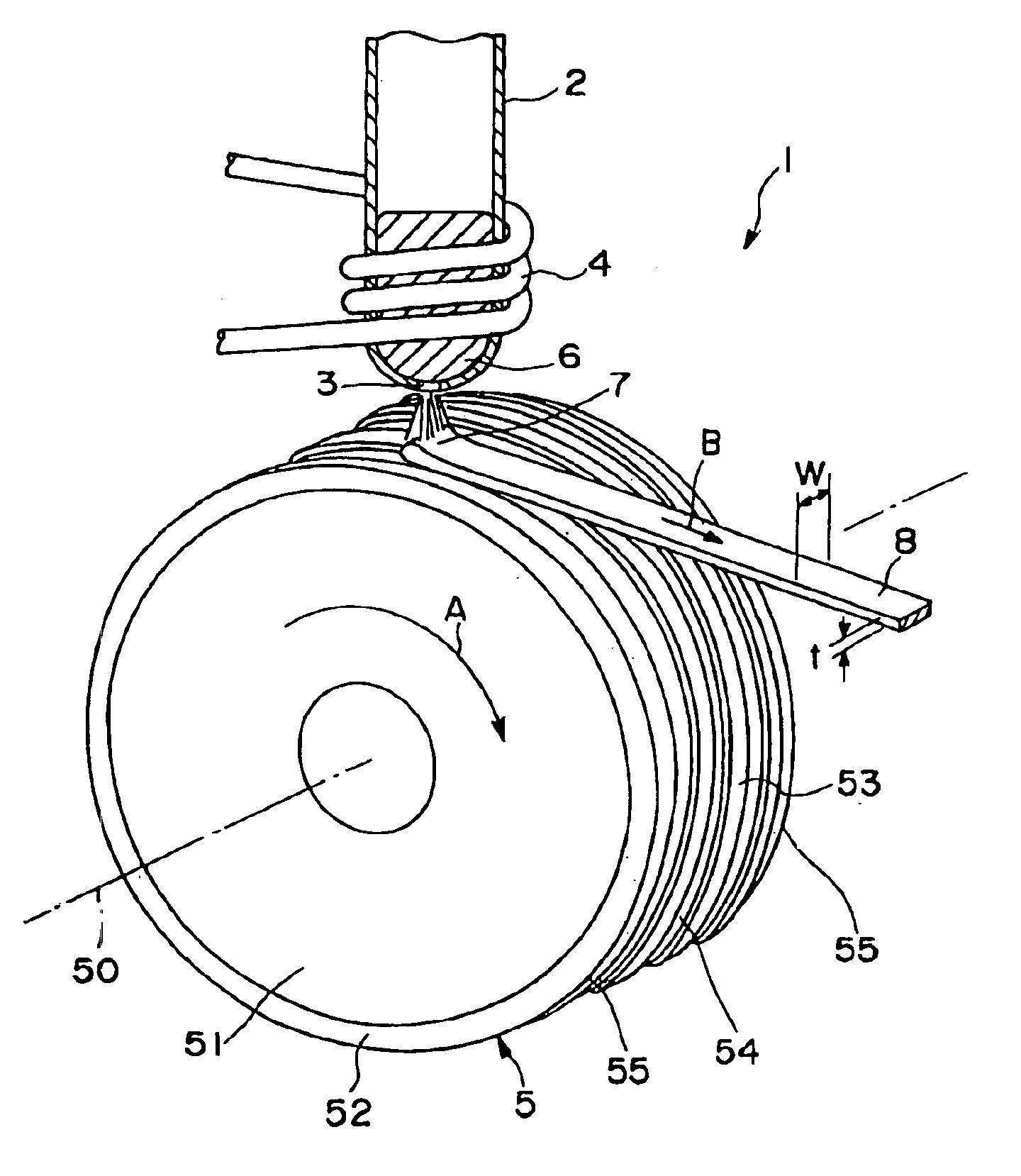
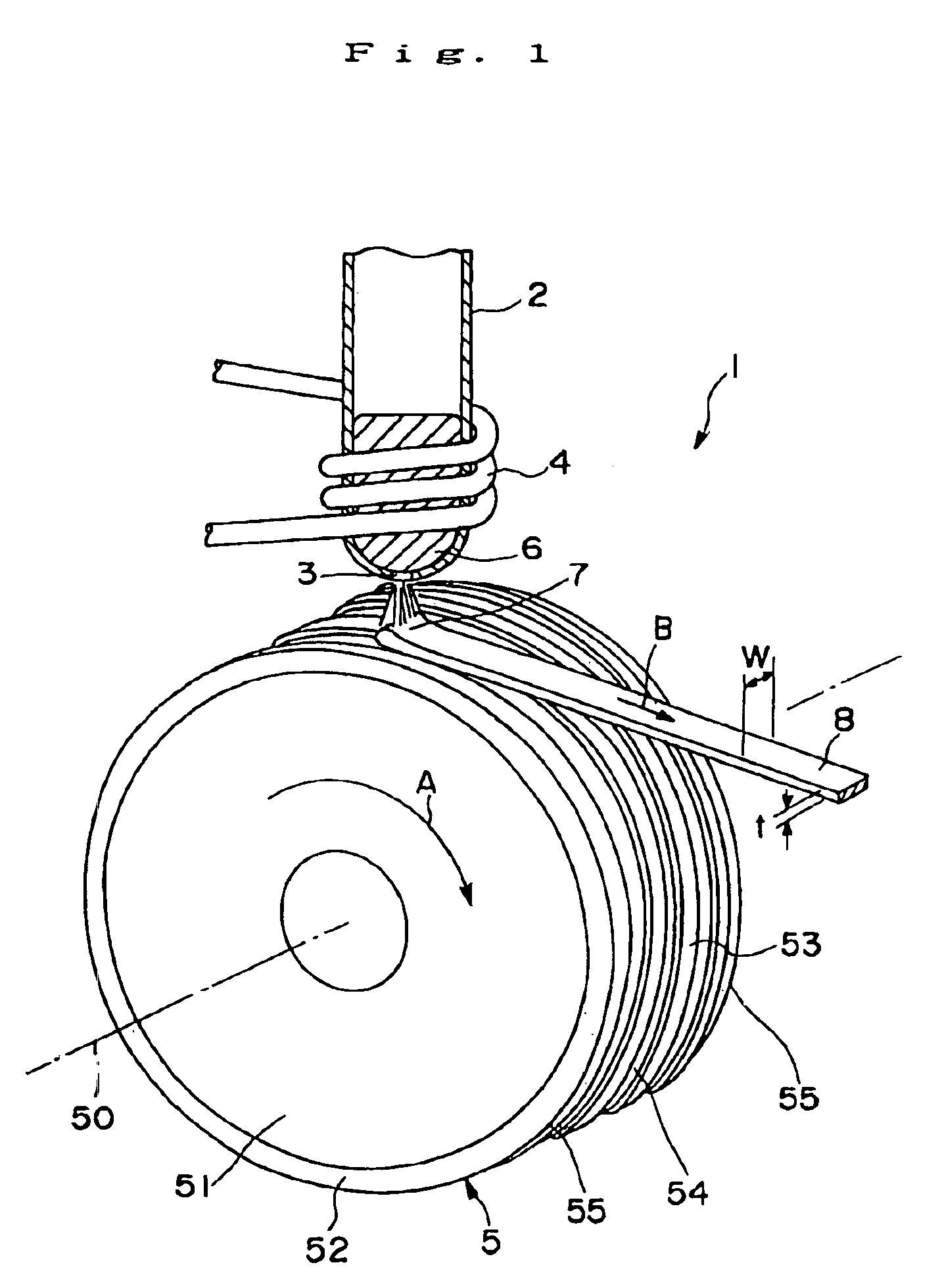
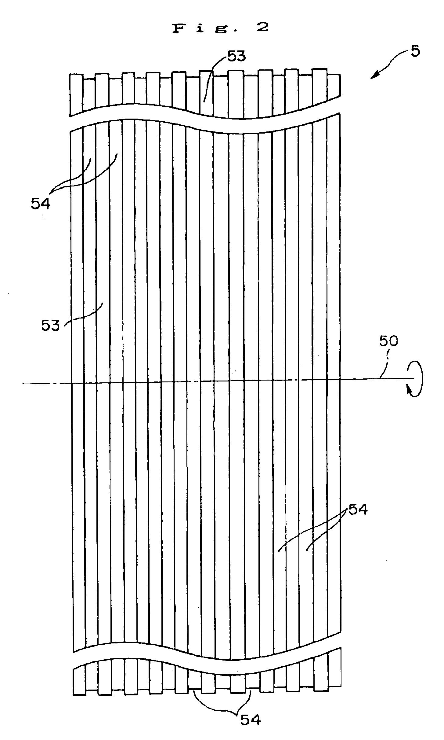
[0177]A cooling roll A having the gas expelling means shown in FIGS. 1 to 3 was manufactured, and then a melt spinning apparatus equipped with the cooling roll A shown in FIG. 1 was prepared.

[0178]The cooling roll A was manufactured as follows.

[0179]First, a roll base (having diameter of 200 mm and width of 30 mm) made of a copper (having heat conductive of 395 W·m−1·K−1 at t a temperature of 20° C. and coefficient of thermal expansion of 16.5×10⁻⁶ K−1 at a temperature of 20° C.) was prepared, and then it was ground so as to have a mirror finishing outer circumferential surface with a surface roughness of Ra 0.07 μm.

[0180]Then, a plurality of grooves 54 which extend in parallel with the rotational direction of the roll base were formed by cutting.

[0181]Next, a surface layer of ZrC (a kind of ceramics) (having heat conductive of 20.6 W·m−1·K−1 at t a temperature of 20° C. and coefficient of thermal expansion of 7.0×10⁻⁶ K−1 at a temperature of 20° C.) was formed onto the outer circum...

example 2

[0209]Ten melt spun ribbons (sample Nos. 2a, 2b, 2c, 2d, 2e, 2f, 2g, 2h, 2i and 2j) were manufactured using the cooling rolls A to J in the same manner as Example 1 described above excepting that the alloy composition of each melt spun ribbon was Nd11.5Febal.B4.6.

[0210]For each of the samples Nos. 2a to 2j, the magnetic properties of the melt spun ribbon was measured in the same manner as Example 1.

[0211]Then, each of the melt spun ribbons was subjected to a heat treatment in an argon gas atmosphere at a temperature of 675° C. for 300 sec.

[0212]Then, each of the melt spun ribbons which were subjected to the heat treatment was milled to obtain magnetic powder having a mean particle size of 70 μm.

[0213]To analyze the phase structure of the obtained magnetic powders, the respective magnetic powder was subjected to an X-ray diffraction test using Cu—Kα line at the diffraction angle (2θ) of 20°-60°. As a result, in each of the magnetic powders, the obtained diffraction pattern shows only...


PUM

PropertyMeasurementUnit
Lengthaaaaaaaaaa
Thicknessaaaaaaaaaa
Angleaaaaaaaaaa

Abstract

Disclosed herein is a method of manufacturing a magnetic material which can provide a bonded magnet having excellent magnetic properties and having excellent reliability. A melt spinning apparatus 1 is provided with a tube 2 having a nozzle 3 at the bottom thereof, a coil 4 for heating the tube and a cooling roll 5 having a circumferential surface 53 in which gas expelling grooves 54 are formed. A melt spun ribbon 8 is formed by injecting the molten alloy 6 from the nozzle 6 so as to be collided with the circumferential surface 53 of the cooling roll 5, so that the molten alloy 6 is cooled and then solidified. In this process, gas is likely to enter between a puddle 7 of the molten alloy 6 and the circumferential surface 53, but such gas is expelled by means of the gas expelling grooves 54.

Description

BACKGROUND OF THE INVENTION[0001]1. Field of the Invention[0002]This invention relates to a method of manufacturing magnetic materials, and ribbon-shaped magnetic materials, powdered magnetic materials and bonded magnets. More specifically, this invention relates to a method of manufacturing magnetic materials, and ribbon-shaped magnetic materials manufactured by the method, powdered magnetic materials formed from the magnetic materials and bonded magnets formed from the powdered magnetic materials.[0003]2. Description of the Prior Art[0004]Rare-earth magnetic materials formed from alloys containing rare-earth elements have high magnetic properties. Therefore, when they are used for magnetic materials for motors, for example, the motors can exhibit high performance.[0005]Such magnetic materials are manufactured by the quenching method using a melt spinning apparatus, for example. Hereinbelow, explanation will be made with regard to the manufacturing method using the melt spinning ap...

Claims


Application Information

Patent Timeline
IPC IPC(8): H01F1/12H01F1/057H01F1/032H01F1/153H01F1/055B22F1/00B22D11/06B22F9/04C22C33/02C22C38/00H01F1/053H01F1/06H01F1/08
CPCH01F1/0551H01F1/0571H01F1/0578H01F1/15341B22D11/0611B22D11/0651B22D11/001C22C2202/02C22C33/02B22F2009/048H01F41/02
Inventor ARAI, AKIRAKATO, HIROSHI
Owner SEIKO EPSON CORP
Why Eureka
Try Eureka