
Digital eye camera

a digital camera and eye technology, applied in the field of digital eye cameras, can solve the problems of large intra-observer variation, difficult assessment of these quantities, faulty examination or diagnosis, etc., and achieve the effect of reducing the stress on patients and clinicians

Inactive Publication Date: 2005-07-26
MASSIE RES LAB
View PDF3 Cites 26 Cited by
  • Summary
  • Abstract
  • Description
  • Claims
  • Application Information

AI Technical Summary

Benefits of technology

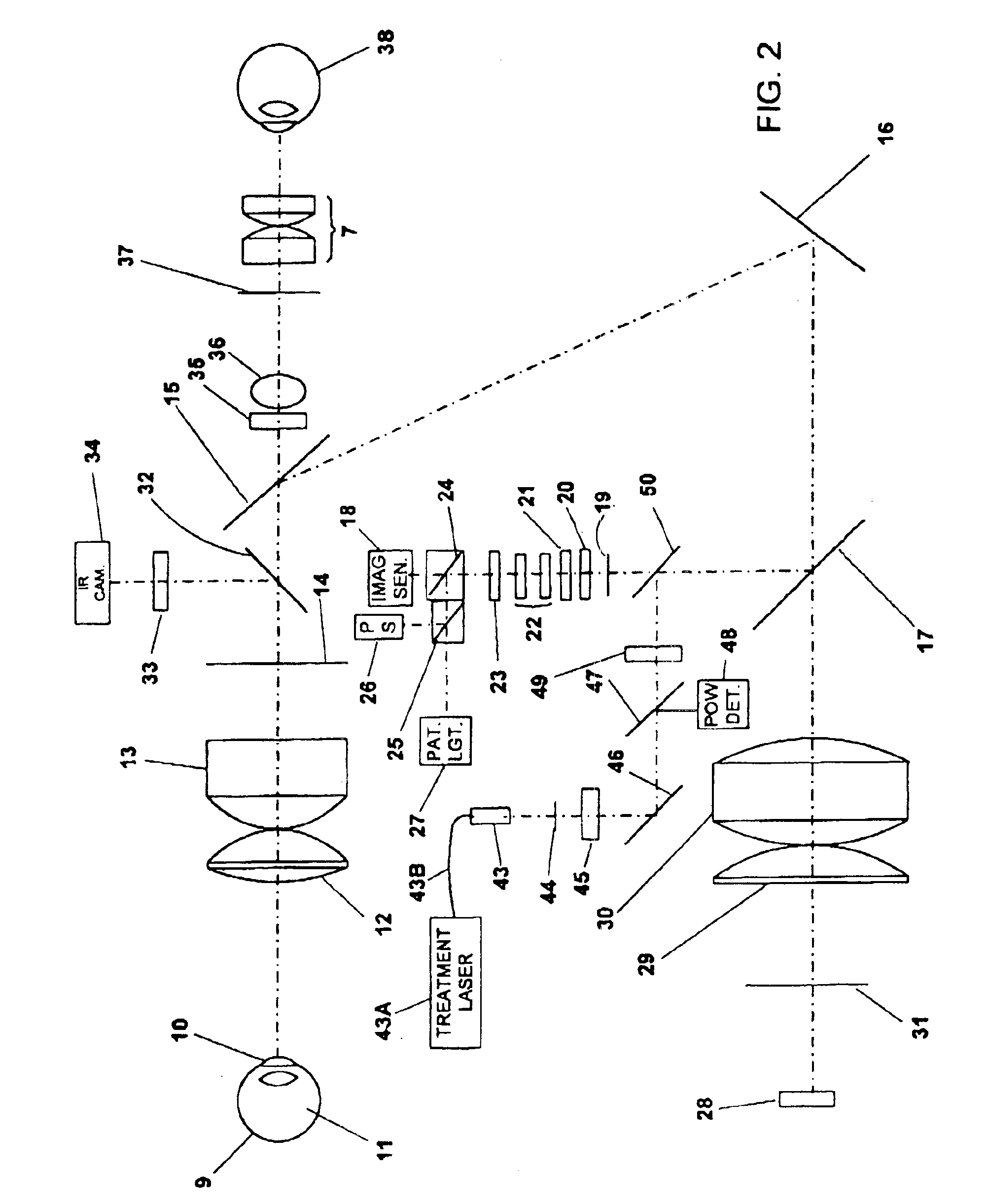
[0018]The switching between the retina, and cornea modes is done internally, while the optical system is sealed by the front lens. The optical system has two different entrance pupils, one located at the leas of the patient's eye for operation in retina mode and another near the front objective lens for operation in the cornea mode. The optical design corrects spherical and achromatic aberrations in both configurations. As the result, the proposed system produces high resolution and high contrast images for both the retinal and cornea regions of the eye.
[0020]Preferably an infrared sensor that continuously images the cornea and co-axially through the optical system while retinal imaging is being conducted to facilitate alignment to a patient's eye which may be moving slightly. This reduces the skill level requirements considerably and provides the option to include sophisticated focus sensors. In remote locations where a highly skilled clinician is not available the patient's eye can be “digitally captured” and this information sent to a reading center for evaluation.
[0023]With this camera the time required for an eye examination is reduced substantially. An image is quickly obtained and with a rather low level of flashed light. Preferably the image is then later examined at leisure and shared with the patient. Images from different dates can be retrieved from the digital storage media The amount of time spent with the doctor looking about the retina is reduced from several minutes to seconds. The camera is especially useful in diagnosing glaucoma in the early phases because of the ease of detecting changes between eye exams in the status of the eye.
[0024]Preferably white LED modules consisting of multiple LEDs will be used as the light sources in both retinal imaging and corneal imaging part of the system. The LED module works either continuously or in pulsed mode. LED modules with different wavelengths will be used as light source for FA and ICG angiograms. A special fiber optical component is used to transform the light output to the shape of ring, resulting in higher light coupling efficiency.
[0025]A preferred embodiment provides an internally integrated laser projection system. The laser light can be projected internally from a plane conjugate to the imaging plane to be used for therapeutic purpose. With the help of the infrared alignment system, the alignment is easy and simple. When the system is switched to the retinal imaging mode, the laser beam with the appropriate beam characteristic would be delivered to the retina region. The illumination to the retina is provided internally and independent of the positions of laser beam. When the system is switched to the corneal imaging mode, the laser would be delivered to the corneal region.
[0027]Because the system alignment, retinal / corneal image and aiming laser spot can be monitored and manipulated by a single joystick in real time remotely, the clinician is free from the restricted posture during the treatment session. The patients can be positioned in a more comfortable position during the procedure. It would greatly reduce the stress imposed on the patients and clinicians.

Problems solved by technology

This lack of documentation leaves open an opportunity for later criticism that the examination or diagnoses was faulty.
Further, it is well known in the instance of estimating the pallor, the cup-to-disk ratio, and the like, that making assessments of these quantities are difficult and that the intra-observer variation is large.
The light is considered uncomfortably bright by most patients and skill is required on the part of the clinician.
It is difficult to simply stop the scan and study a given area such as the optical disk because of patient motion and discomfort.
However, like the direct ophthalmoscope, the doctor must develop a mental picture of the broader features of the eye and, because of the bright light and movements of the patient's eye, it is difficult to stop and carefully study one portion of the retina.
However, when modified for retinal imaging, its inherent limitations generally prevent it from providing high quality retinal visualizations.
The lens is positioned to be very close to the patient's eye, which in turn makes it very difficult to determine and adjust the alignment for the lens.
The contact type lens can be very uncomfortable to the patients.
The lens produces strong light reflection from its surfaces, which deteriorate the quality of retinal image greatly.
However, with only a slit of light, only small portions of the retina can be observed at a time and patients generally feel that the light intensity if very uncomfortable.
Overall, modifications on the slit lamp biomicroscope produce a very substandard retinal visualization system.
Further, dilation is very objectionable to patients because of the elapsed time for the dilation to return to normal.
Most patients also find the brightness of the light objectionable and many times to the point of pain.
While some BIO's come equipped with head-mounted cameras, these have not been widely accepted, are regarded as difficult to use, and only image a small portion of the retina at a time in any instance.
A hazard of dilation is the risk of inducing acute glaucoma that can lead to immediate blindness.
Film has the disadvantage of requiring processing before an assessment of image quality can be obtained and there is no ability to immediately electronically transfer the image.
In current practice these digital add-ons to existing cameras and are quite bulky and expensive.
The high level of acquisition and operating costs for digital cameras has left digital imaging to the domain of high-end clinical sites and they are not used for routine exams.
Digital cameras have also been added to slit-lamp biomicroscopes so that they can be used for imaging, but this single purpose application has generally proved to not be cost effective and is seldom implemented.
However, the camera generally produces low quality pictures because the inherent achromatic and spherical optical aberrations when used with an air path and are high and the camera has only a very limit working range.
When the cornea is in focus, the patient's eye is located so close to the camera that it becomes difficult to place a slit-lamp between them and no known commercial product provides a slit-lamp with the fundus camera.
The built-in internal magnification adjustment for the fundus camera is not adequately designed for the required magnifications of corneal imaging.
Thus, as a practical matter, using the fundus camera for corneal imaging is very non-optimal.
These imaging systems, commonly called a scanning laser ophthalmoscope or SLO, usually only provide one laser wavelength a add this therefore does not produce a color image, a significant clinical disadvantage.
Recently, a system was provided to the market with two laser colors, but even this produces very, very poor color image quality.
Even greater limitations are in the relatively long exposure time that allows eye movement during the frame time, the large size, and the high cost.
This is a very challenging task.
Although it provides a more stable condition for laser procedure, the external attachment makes the system complicated to use.
It is not comfortable to hold the laser lens steady during the long laser treatment session which can last for several minutes.
In addition, the reflected laser light from the laser lens can scatter back in many directions in the room, a result hazardous to others present.
As result, there is the risk of accidentally firing the laser on to the iris.
The nature of the manual manipulation of the laser beam also makes it difficult to assess the dosage of laser being delivered to the retina if no clear marks are left after the treatment.
Sometimes, a completely separate system is provided for laser treatment, adding to the expense to well equip an eye doctors office.

Method used


Image

  • Digital eye camera
  • Digital eye camera
  • Digital eye camera

Examples


first preferred embodiment external

Design

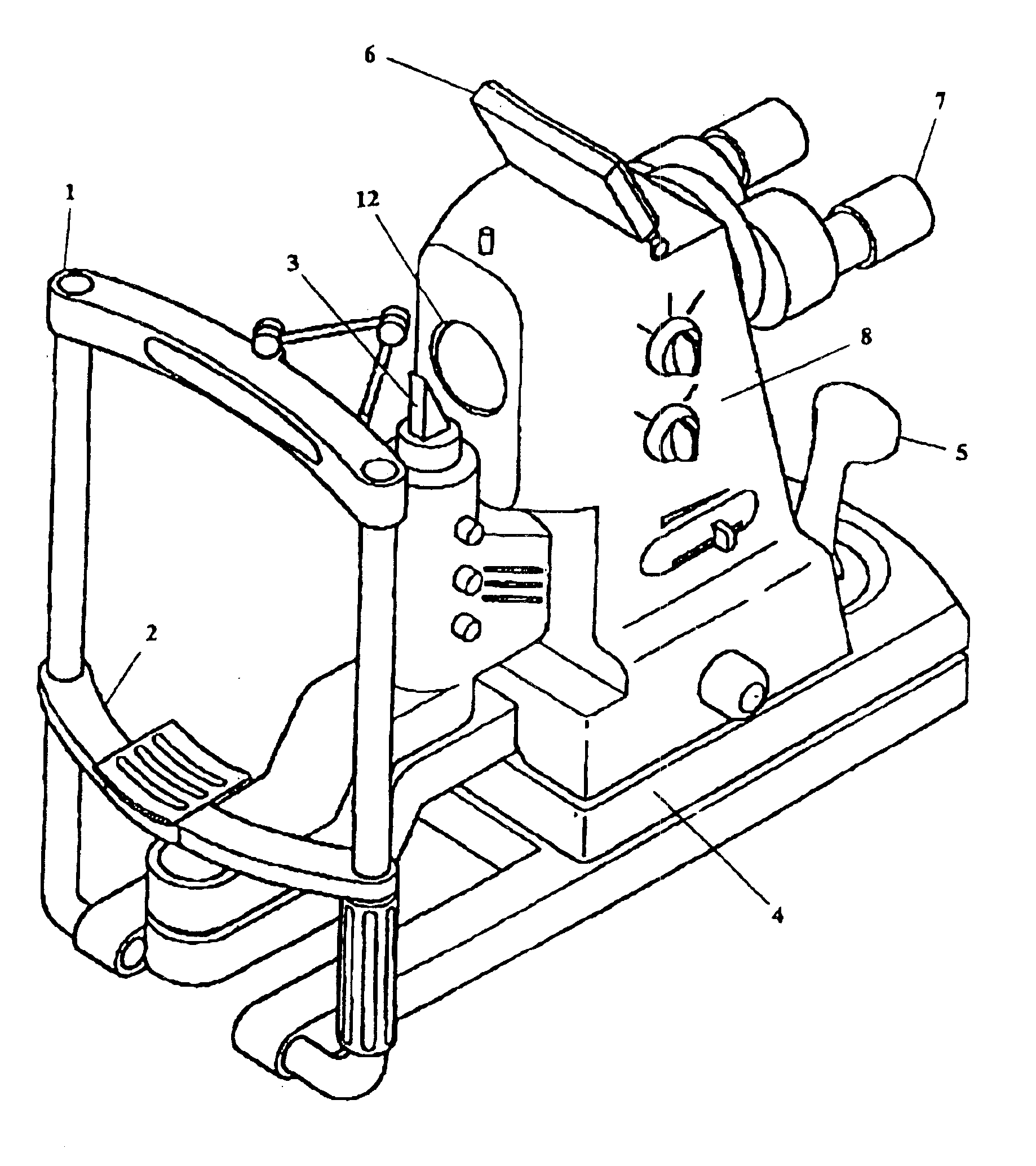
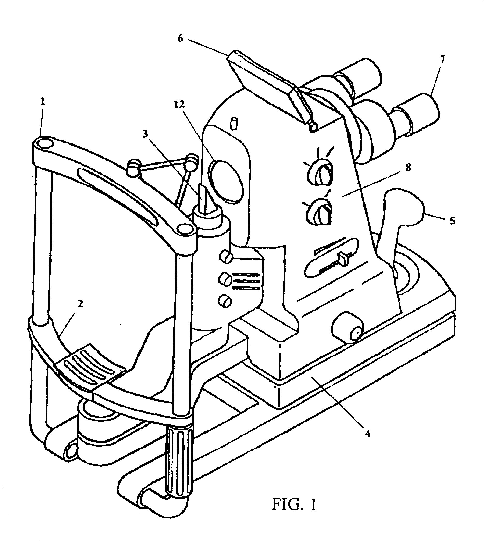
[0033]In FIG. 1 is shown the exterior design of a first preferred embodiment of the present invention. A typical headrest 1 and chin rest 2 is provided to stabilize the patient head. The slit lamp 3 provides illumination for examination of the cornea and is adjustable in brightness, color, and width of slit.

[0034]The base 4 provides the usual degrees of freedom in angular, transverse and longitudinal motion. Inside of the camera are means for adjusting the height of the camera potentially through a motorized system. Joystick 5 assists in controlling motion and has control switches for operation of the system. In FIG. 1, the joystick 5 is shown on base 4. Alternatively, the joystick S can be mounted on a portable base, and be placed on different position away from the base 4.

[0035]A small LCD display 6 can be used to display the image, especially a real-time infrared corneal image. However, the main image display is a larger monitor and is not shown. Oculars 7 are provided for ...


PUM


Abstract

A digital camera that combines the functions of the retinal camera and corneal camera into one, single, small, easy to use instrument. The single camera can acquire digital images of a retinal region of an eye, and digital images of a corneal region of the eye. The camera includes a first combination of optical elements for making said retinal digital images, and a second combination of optical elements for making said corneal digital images. In a preferred embodiment, a portion of these elements are shared elements including a first objective element of an objective lens combination, a digital image sensor and at least one eyepiece for viewing either the retina or the cornea. Also, preferably, the retinal combination also includes a first changeable element of said objective lens system for focusing, in combination with said first objective element, portions or all of said retinal region at or approximately at a common image plane. Also, preferably, the retinal combination also includes a retinal illuminating light source, an aperture within said fame and positioned within said first combination to form an effective retinal aperture located at or approximately at the lens of the eye defining an effective retinal aperture position, an infrared camera for determining eye position, and an aperture adjustment mechanism for adjusting the effective retinal aperture based on position signals from said infrared camera. Also, preferably, the cornea combination of elements includes a second changeable element of said objective lens system for focusing, in combination with said first objective element, portions or all of said cornea region at or approximately at a common image plane.

Description

[0001]This application is a continuation application of Ser. No. 10 / 033,432 filed Dec. 26, 2001 U.S. Pat. No. 6,685,317 which is a continuation application of Ser. No. 09 / 592,899 filed Jun. 13, 2000, now U.S. Pat. No. 6,361,167. Both applications are hereby incorporated by reference for all purposes.BACKGROUND OF THE INVENTIONEye Examinations[0002]Eye health-care practitioners generally divide patient examination into three parts: examination of the cornea, examination of the retina, and a vision function exam including measurement of the refractive status of the eye. The doctor's findings need to be recorded and the standard method for last century has been to make hand-written notes in the chart. Hand recording of vision function and refractive status is completely satisfactory. Vision function is basically a quantitative assessment by the doctor and six numbers describe the refractive information of both eyes so that the manual recording process is quick and efficient. Recording ...

Claims


Application Information

Patent Timeline
Patent Type & Authority Patents(United States)
IPC IPC(8): A61B3/12A61B3/14A61B3/135A61B3/13A61B3/117A61B5/00A61B3/10A61B3/107A61B18/18A61F9/01
CPCA61F9/008A61B3/154A61B3/14A61B3/0008A61B3/12A61B3/152A61B5/0002A61F9/00817A61F2009/00844A61F2009/00846A61F2009/00872A61F2009/00863
Inventor SU, WEIMASSLE, NORBERT A.
Owner MASSIE RES LAB
Learn More