Method for the continuous production of methyl formate

a technology of methyl formate and continuous production, which is applied in the direction of separation processes, organic chemistry, pressurized chemical processes, etc., can solve the problems of virtually insoluble engineering problems, high equipment requirements, and inability to meet the requirements of continuous production, and achieves good yields and low equipment requirements.

Inactive Publication Date: 2005-07-26
BASF AG
View PDF29 Cites 11 Cited by
  • Summary
  • Abstract
  • Description
  • Claims
  • Application Information

AI Technical Summary

Benefits of technology

[0024]It has now surprisingly been found that methyl formate can be prepared in a trouble-free manner, in goo

Problems solved by technology

However, the industrial implementation of this process suffers from problems which make the process inconvenient, unreliable and energy-consuming and thus considerably increase its costs.
A high outlay in terms of apparatus is required for carrying out this known process; in particular, stirring under the high pressure results in virtually insoluble engineering problems.
Despite the high engineering outlay, it is not possible to prevent the difficulties associated with the formation of solid deposits in this process either.
Trouble-free continuous operation of the process for acceptable periods of time is therefore not possible.
For this reason, the production capacity achievable in practice is unsatisfactory and the process as a whole is uneconomical.
The reaction mixture obtained in the first stage is then reacted with an excess of CO in an autoclave until a conversion to methyl formate of about 90%, based on methanol used, has been achieved. in this process, it is difficult to ensure the conditions required in the reactor, namely maintenance of a particular reaction temperature with simultaneous turbulent flow.
In addition, industrial implementation of the process requires very difficult, very exact control of the cooling water temperature, the CO pressure and the flow velocity of the reactants.
Although a production capacity of 1674 kg/m3/h has been derived purely mathematically in the working example, this process, too, could not be introduced for continuous production of methyl formate because of the high engineering outlay, the tremendous difficulties in setting and monitoring the process conditions and the remaining intrinsic risk of blockages.
However, according to the working example, this process gives a production capacity of only about 440 kg/m3/h in a limited-term individual experiment.
Despite this, deposits of catalyst and its decomposition products on plant components cannot be avoided over a prolonged operating time, which results in downtimes and a further reduction in the product capacity.
However, recirculation of the catalyst is not provided for, so that relatively large amounts of solid waste are formed after work-up of the crude product despite the low catalyst concentration.
Furthermore, exploitation of the high conversion which is possible in principle involves an appreciable risk of deposition of encrustations in the plant, so that here, too, one has to expect plant downtimes which will drastically reduce the intrinsically good production capacities determined in individual experiments.
In addition, the capital costs of the plant are high because of the high process pressures, so that the economics of the process are not fully satisfactory.
The abovementioned high-pressure processes make it possible to achieve a high methanol and CO conversion, but lead to t

Method used


Image

  • Method for the continuous production of methyl formate
  • Method for the continuous production of methyl formate

Examples


example 1

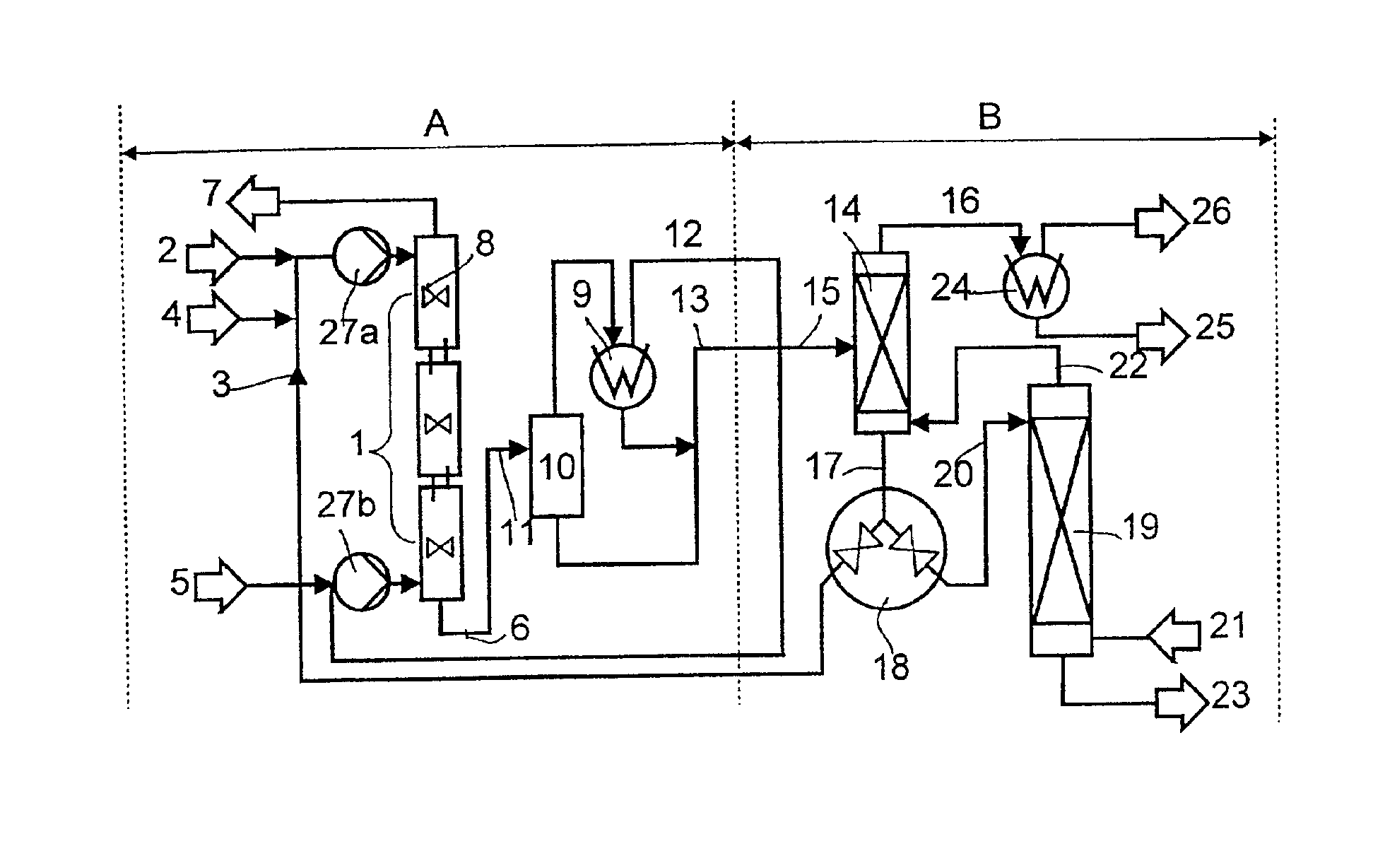
[0106]Three upright tube reactors each having a volume of 2 l and each fitted with an external circuit with heat exchangers, feed lines for liquid phase and outlet lines for gas phase in the top region and outlet lines for liquid phase and jet nozzle inlets for gas phase in the bottom region were connected in series above one another so that gas phase introduced at the bottom of the lowermost reactor can flow upward through all three reactors in succession and liquid phase fed in in the top region of the uppermost reactor can flow downward through all three reactors in succession.

[0107]This synthesis arrangement was used to carry out 12 experiments in which methanol and catalyst in the form of a methanolic alkali metal methoxide solution were fed in at the top of the reactor cascade and CO was fed in from below via the jet nozzles. The feed flows are indicated in Table 1. The pressure and the temperature in the reactors were set to the values likewise shown in Table 1.

[0108]The prod...

example 2

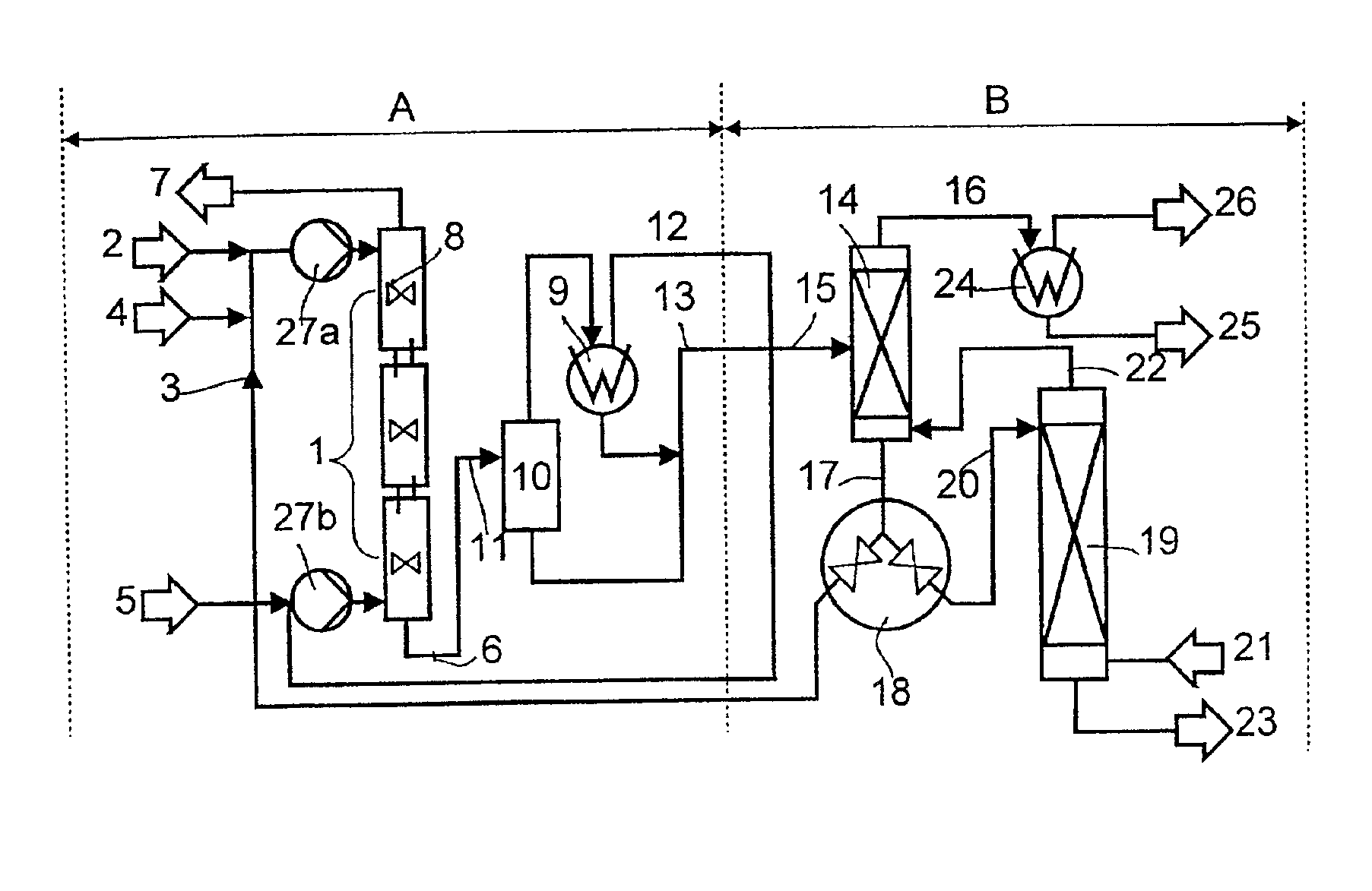
[0116]Two tube reactors having a length of 200 cm and an internal diameter of 4.5 cm (volume=3.15 l) and provided with an internal heat exchange tube, inlets for liquid and gas phase in the bottom region and outlets for liquid and gas phase in the top region, with the inlets for the gas phase being configured as jet nozzles, were connected in series above one another in such a way that liquid phase and gas phase introduced at the bottom of the lowermost reactor can flow upward in cocurrent through all three reactors in succession.

[0117]This synthesis arrangement was used to carry out 19 experiments in which methanol, catalyst in the form of a methanolic alkali metal methoxide solution and, through the jet nozzle, CO were fed from the bottom into the reactor cascade. The feed flows are indicated in Table 2. The pressure and the temperature in the reactors were set to the values likewise shown in Table 2.

[0118]The last 4 columns of Table 2 show the experimental results obtained.

[0119]...


PUM

PropertyMeasurementUnit
Temperatureaaaaaaaaaa
Fractionaaaaaaaaaa

Abstract

A description is given of a process for preparing methyl formate by reacting excess methanol with carbon monoxide under superatmospheric pressure and at elevated temperature in the presence of alkali metal methoxide or alkaline earth metal methoxide as catalyst in a pressure-rated reactor, in which the use of at least two reactor elements, preferably operated in countercurrent, at about 100° C. and a pressure of about 100 bar in combination with a solids-free desalting of the reaction product makes possible very economical, largely trouble-free production of methyl formate in any desired quality and with a very good production capacity.
Furthermore, the process for solids-free desalting and apparatuses for carrying out this process are described.

Description

BACKGROUND OF THE INVENTION[0001]The present invention relates to a process for preparing methyl formate, to an apparatus for carrying out this process and to methyl formate which has been prepared by this process and is to be used, in particular, for preparing formic acid.[0002]Methyl formate is used in industry predominantly for the preparation of formic acid and for this purpose is at present produced on a large scale by reaction of methanol with carbon monoxide in the presence of alkali metal alkoxide. However, the industrial implementation of this process suffers from problems which make the process inconvenient, unreliable and energy-consuming and thus considerably increase its costs.[0003]To seek to perfect the process for industrial-scale use, the technology for carrying out the process has developed in essentially two directions: one group of processes employs a very high CO pressure with the aim of obtaining very high concentrations of methyl formate in the output from the...

Claims


Application Information

Patent Timeline
IPC IPC(8): C07C67/36C07C67/00B01D3/00B01J3/00B01J3/02B01J19/00C07B61/00C07C29/80C07C31/04C07C69/06
CPCC07C67/36C07C69/06
Inventor AUER, HEINZDAHLHAUS, JURGENFISCHER, KARLHAMMER, HANSKELLENBENZ, JOCHENSCHULZ, MICHAELTHIEL, JOACHIMVICARI, MAXIMILIAN
Owner BASF AG
Why Eureka
Try Eureka