Thrombectomy and tissue removal method

a thrombosis and tissue technology, applied in the field of medical devices and procedures, to achieve the effect of effective breaking up the thrombosis or tissue deposit, low localized pressure, and high velocity

Inactive Publication Date: 2005-08-09
MEDRAD INC.
View PDF6 Cites 74 Cited by
  • Summary
  • Abstract
  • Description
  • Claims
  • Application Information

AI Technical Summary

Benefits of technology

[0019]According to the sixth embodiment of the invention (FIG. 16), there is provided a thrombus or tissue fragmentation catheter that does not remove the fragmented thrombus or tissue. The device contains a high pressure fluid tube such as a hypo tube which delivers high pressure fluid to one or more orifices which direct jet(s) of fluid proximally toward the surface. The surface serves as a target for the jet(s), providing an element of safety to the catheter by prohibiting direct impingement of the jet(s) on the wall of a blood vessel, tubule or duct. The jet(s) have high velocity and low localized pressure due to the high fluid pressure of at least 500 psi in the high pressure tube. Therefore, the jet(s) can both entrain thrombus or tissue onto the jet(s), and break up the tissue or thrombus into fragments. No lumen is available in this catheter for exhaust of the fragments. The impingement surface can be made with an opening, which would allow for guidewire passage, although it is not required. The distal end of the hypo tube can be made into a loop to provide for guidewire passage, although it is not required. Fragments generated by this device can be allowed to remain in the vessel, tubule, or cavity, and may embolize with blood flow, or may be washed out using other means.
[0020]According to the seventh embodiment of the invention, which applies to previous embodiments that contain an exhaust lumen, there is provided a catheter with a high pressure tube to deliver high pressure fluid from the proximal end of the catheter to the distal end where the fluid is directed by one or more orifices at high velocity onto the distal opening of an exhaust lumen. The pressure in the high pressure tubing at the distal end is at least 500 psi in order to effectively break up the thrombus or tissue deposit. A suction may be applied to the proximal end of the exhaust lumen with a vacuum pump to provide for removal of the fragmented thrombus or tissue, or a roller pump may be used to accomplish a similar effect. The pressure in the high pressure tubing at the distal end may be greater than 500 psi with improved tissue fragmentation occurring at pressures over 1000 psi. Entrainment of tissue such as thrombus into the localized low pressure region of the high velocity jet(s) allows the device to operate effectively without requiring direct contact or juxtaposition of the catheter with neighboring tissue deposit. The distal end of the high pressure tube may form a small arc in order to direct the jet(s) of high pressure fluid proximally toward the opening of the exhaust lumen, or it may form a loop perpendicular to the axis of the catheter shaft in order to direct several jets of fluid rearwards. The loop allows the catheter to follow over a guidewire to reach the lesion site and to effectively fragment thrombus or tissue around the entire perimeter of the guidewire, vessel, tubule, or body cavity.

Problems solved by technology

This may be of greater importance if immobilization of fragmented debris may generate unfavorable clinical sequelae.

Method used


Image

  • Thrombectomy and tissue removal method
  • Thrombectomy and tissue removal method
  • Thrombectomy and tissue removal method

Examples


Embodiment Construction

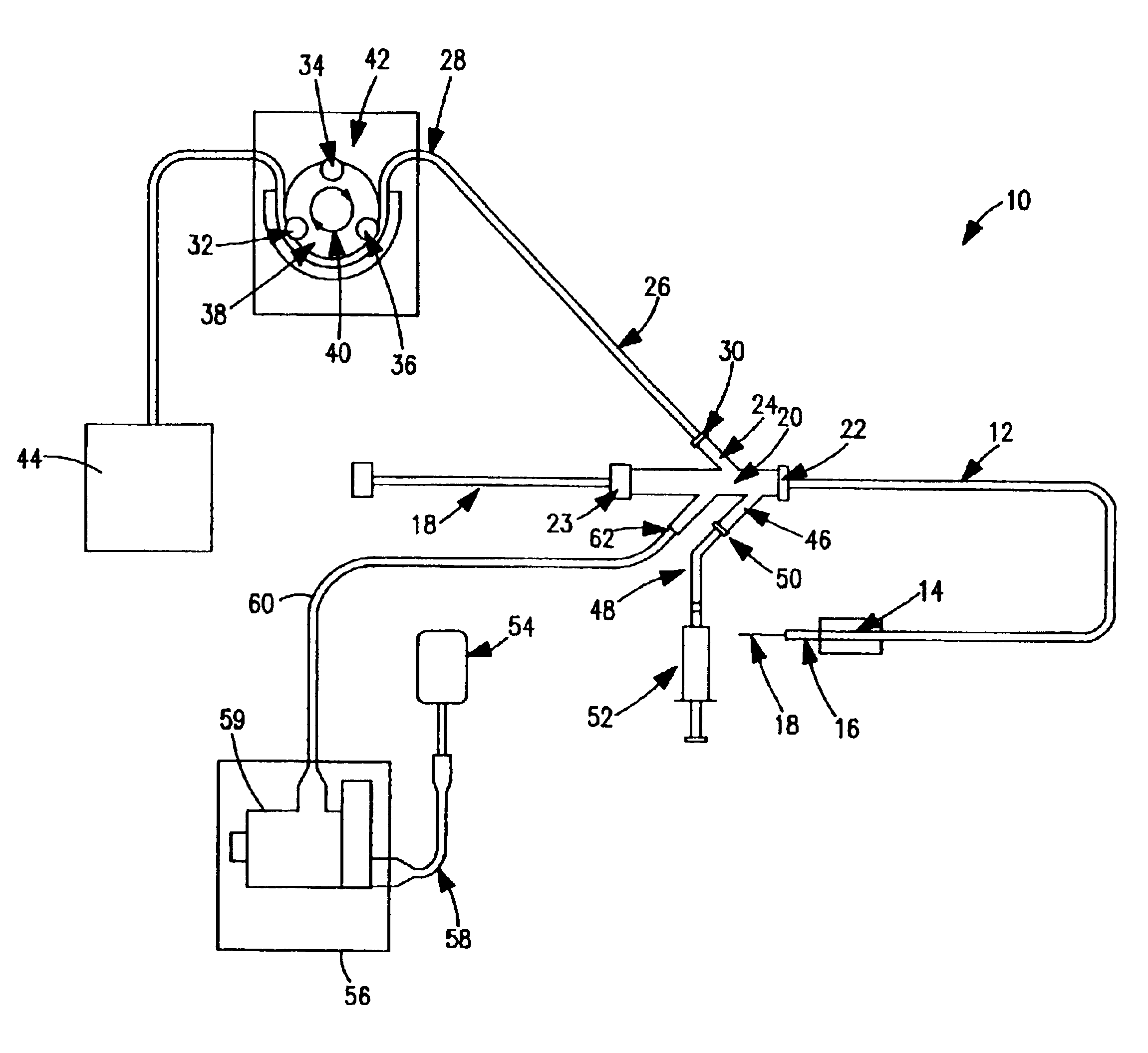
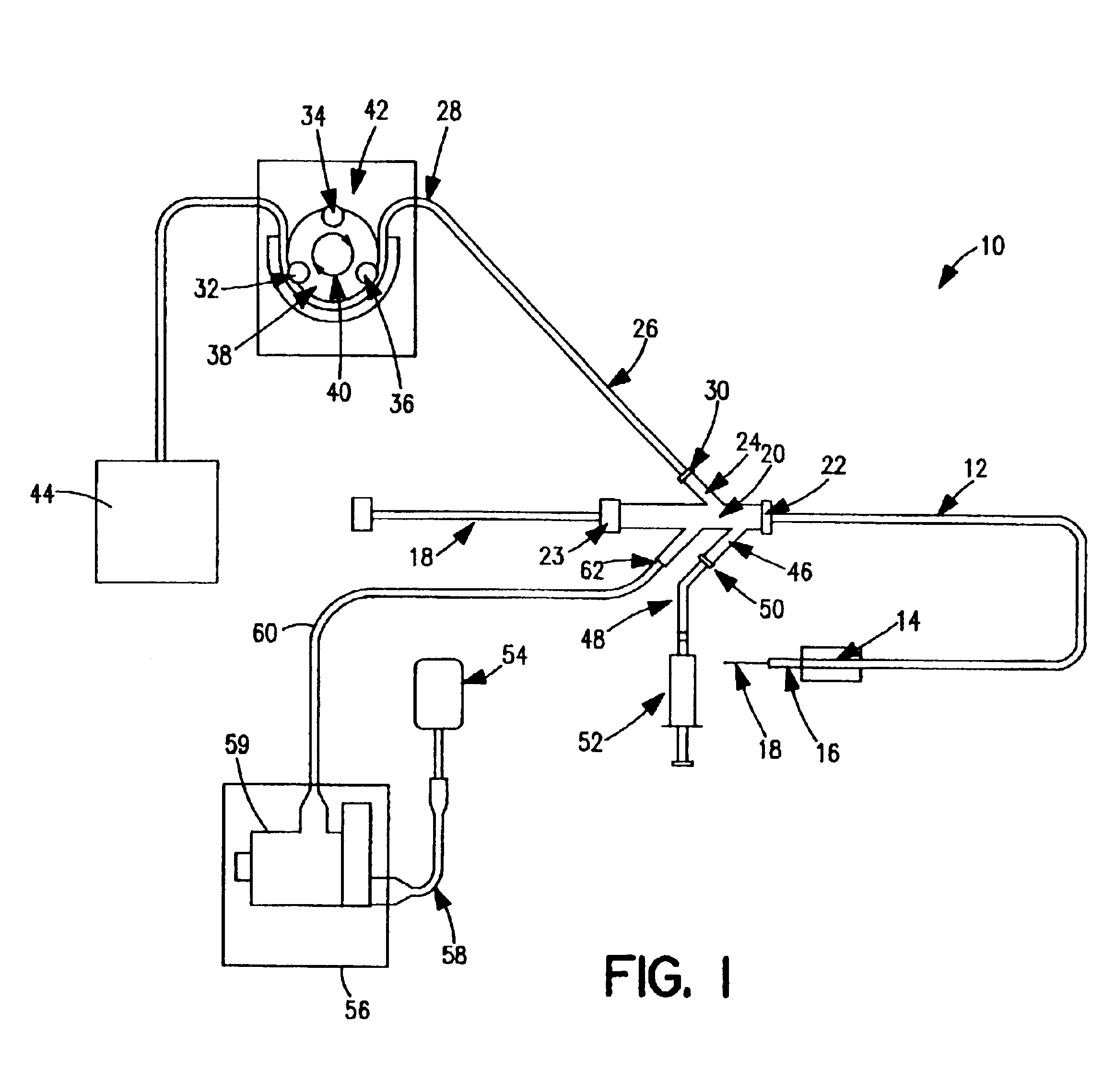
[0039]FIG. 1 is a schematic view of one embodiment of a thrombectomy and tissue removal device 10 according to the present invention. The details supplied herein should be taken as representative and not limiting of the many embodiments which may be efficaciously employed within the scope of the present invention.

[0040]Thrombectomy and tissue removal device 10 has a two-passage tubular member such as a standard two-lumen catheter 12, which is extruded of a flexible material such as polyolefin, PTFE, PVC, polyurethane, nylon, or other suitable material in the normal fashion. Near the distal end 16 of catheter 12 can be located inflatable balloon 14, which is preferably an elastic balloon having no predefined outside diameter size limitation upon inflation. In this manner, balloon 14 can conform to the exact dimensions of the vessel to hold distal end 16 of catheter 12 in a fixed position. Alternatively, inflatable balloon 14 can be an inelastic balloon with a predefined shape and siz...


PUM


Abstract

A method for removing thrombus or other material from a natural or synthetic body vessel or cavity without the need for direct surgical access. The method includes providing a device supplying high pressure fluid to at least one distal orifice, causing high pressure fluid to emanate from the orifice creating at least one fluid jet, and using the fluid jet to break up material in the vessel. The method further includes directing at least one fluid jet at the opening of an exhaust lumen or target incorporated into the device and using the jet to provide a localized negative pressure which entrains material into the jet for break-up. The method optionally includes using the jet to provide stagnation pressure which drives material along the exhaust lumen. The method optionally includes metering the exhaust to match the fluid input or to be greater or less than the input. A positive displacement pump operating at steady or pulsatile flow provides the high pressure saline to the distal end of the catheter.

Description

CROSS REFERENCES TO CO-PENDING APPLICATIONS[0001]This patent application is a continuation in part application of Ser. No. 08 / 351,613 filed Dec. 8, 1994, U.S. Pat. No. 6,544,209, which is a divisional application of Ser. No. 07 / 976,367 filed Nov. 13, 1992, now abandoned, which is a continuation application of Ser. No. 07 / 563,313 filed Aug. 6, 1990, now abandoned.BACKGROUND OF THE INVENTION[0002]1. Field of the Invention[0003]The present invention relates generally to medical devices and procedures, and more particularly, relates to medical devices and procedures for removing thrombus or other tissue deposits from the cardiovascular system, or from a natural or synthetic tubule or other cavity or synthetic body vessel found in the human body.[0004]2. Description of the Prior Art[0005]Procedures and apparatus have been developed for ease in removing various tissue. U.S. Pat. No. 4,790,813 issued to Kensey and U.S. Pat. No. 4,842,579 issued to Shiber describe techniques for the removal...

Claims


Application Information

Patent Timeline
Patent Type & Authority Patents(United States)
IPC IPC(8): A61B17/22A61B17/32A61B17/00A61M25/00
CPCA61B17/32037A61B17/3203
Inventor DRASLER, WILLIAM J.DUTCHER, ROBERT G.JENSON, MARK L.THIELEN, JOSEPH M.PROTONOTARIOS, EMMANUIL I.
Owner MEDRAD INC.
Why Eureka
Try Eureka