
Dense, layered membranes for hydrogen separation

a hydrogen separation and layered technology, applied in chemical/physical/physical-chemical stationary reactors, metal/metal-oxide/metal-hydroxide catalysts, bulk chemical production, etc., can solve the problem of long operational life under actual operating conditions, and achieve significant hydrogen permeability, minimize harmful interdiffusion, and minimize interdiffusion

Inactive Publication Date: 2006-02-21
ELTRON RES
View PDF62 Cites 71 Cited by
  • Summary
  • Abstract
  • Description
  • Claims
  • Application Information

AI Technical Summary

Benefits of technology

[0030]The dense or non-porous membranes of this invention are formed from a plurality of different layers which together function to achieve hydrogen separation, and in addition to provide suitable mechanical stability, provide resistance to poisoning by non-hydrogen feed-gas components or contaminants, and / or minimize membrane embrittlement by hydrogen. The multi-layered membrane is operationally positioned between a hydrogen-containing feedstream (e.g., a hydrogen-containing gas) and a hydrogen sink and as such has a surface in contact with (e.g., in fluid communication with) the hydrogen feedstream and a surface in contact with the hydrogen sink.
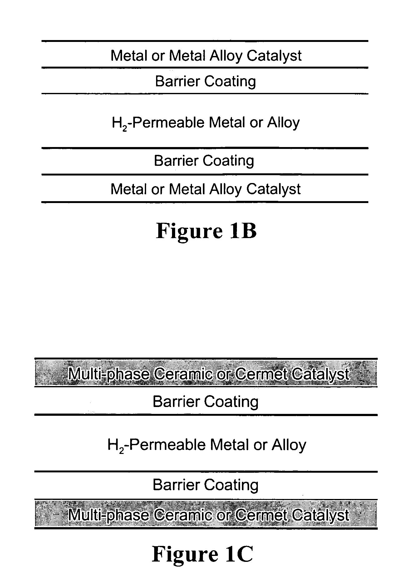
[0034]one or more barrier layers, which may be formed of the same or different materials, which minimize detrimental interdiffusion between the catalyst layer and the NPSP layer, positioned between the first catalyst layer and the NPSP layer or between any second catalyst layer and the NPSP layer.
[0048]Protective layers are porous metal oxide layers which if present are positioned as the outermost layers of the multi-layer hydrogen-permeable membranes. The protective layers protect the catalyst and NPSP layers from the detrimental effects of feedstream and other contaminants that may enter the membrane reactor system. For example, the protective layers can minimize undesired deposition of metals from the feedstream or from metal equipment, tubing or plumbing used in the membrane reactor system onto the catalyst or NPSP layer. Exemplary protective layers include alumina, zirconia, or other metal oxides. Additionally activated carbon or zeolites can be employed. Protective layers can also provide protection from chemical contaminants in the feedstock that would detrimentally affect membrane layer function. In particular, a metal oxide that forms stable sulfides can be used to protect the membrane from sulfur-containing compounds. For example, a protectively layer of porous ZnO, La2O3, SrO, CeO2, or perovskites such as SrCeO3 or La1-xSrxCoO3-δ (where 0≦x≦1 and δ is a number that renders the material charge neutral) can be used to protect the catalyst and NPSP layers from poisoning by sulfur-containing species, including hydrogen sulfide. Hydrogen sulfide dissociation is promoted by addition of copper to the metal oxide of the protective layer. In additional examples, a protective layer comprising a ceramic or other material that absorbs or decomposes water or hydrocarbons can be provided.
[0051]Hydrogen-permeable barrier layers are provided to minimize detrimental interdiffusion between the catalyst layer or layers and the NPSP layer at operating temperatures of the membrane. The barrier layers are ceramic or cermet layers sufficiently thin or porous to allow hydrogen permeation without allowing contact between metals or metal phases of the adjacent layers. The barrier layers may have some porosity, as noted, but are preferably non-porous or dense to minimize interdiffusion. Preferred barrier materials exhibit significant hydrogen permeability. Barrier layers are more preferably employed when either the catalyst layer or the NPSP layer are metals (or alloys) or cermets which contain high levels of metal (e.g. cermets with about 60 vol. % or more of metal).

Problems solved by technology

However, there remains a significant need in the art for membranes that are selectively permeable to hydrogen which exhibit high permeation rates or permeability and which exhibit long operational lifetimes under actual operating conditions.

Method used


Image

  • Dense, layered membranes for hydrogen separation
  • Dense, layered membranes for hydrogen separation
  • Dense, layered membranes for hydrogen separation

Examples


example 1

Preparation of Dense Vanadium-Containing Cermet Membranes

[0166]Cermets are prepared by combining selected amounts of powders of vanadium and a selected ceramic optionally in further combination with a sintering aid and optionally in further combination with an organic binder. The combined powders are formed into selected shapes, e.g., by pressing and the shaped cermets are sintered in vacuum or inert gas at an appropriate temperature until dense. Sintering agents and organic binders are employed, as is known in the art, as needed to achieve densification. When sintering agents are employed, typically 0.5 to 4 wt. % of the sintering agent may remain in the sintered material.

[0167]Sintered shaped cermets are ground to a selected thickness and provided with catalyst layers, typically applied as thin layers by, for example, metal deposition.

[0168]Vanadium-alumina cermets are prepared by combining powders of vanadium metal and alumina in combination with Y2O3 as a sintering aide and poly...

example 2

Hydrogen Permeation Characteristics of Composite Barrier Coatings

[0176]To function as barrier coatings, ceramics, cermets, and inorganic salts must exhibit sufficient hydrogen permeability. Accordingly, a series of membranes were prepared from barrier coating materials and selective hydrogen flux across the membranes was measured. Examples for each category of barrier coating are provided below.

[0177]Ceramic Composites. FIG. 6 shows the ambipolar conductivity (i.e., mixed hydrogen ion / electron conductivity) of four perovskite-based ceramics, each with a different B-site dopant, B′, at a fixed concentration. The general composition for these ceramics is BaCe0.8B′0.2O3-δ. Within this series, there is a gradual increase in ambipolar conductivity from 1.1×10⁻⁴ to 3.3×10⁻⁴ S / cm for the first three compositions as the transition metal dopant moved from left to right across the periodic table (i.e., V to Fe). However, a more substantial increase in conductivity to 6×10⁻³ S / cm is observed f...

example 3

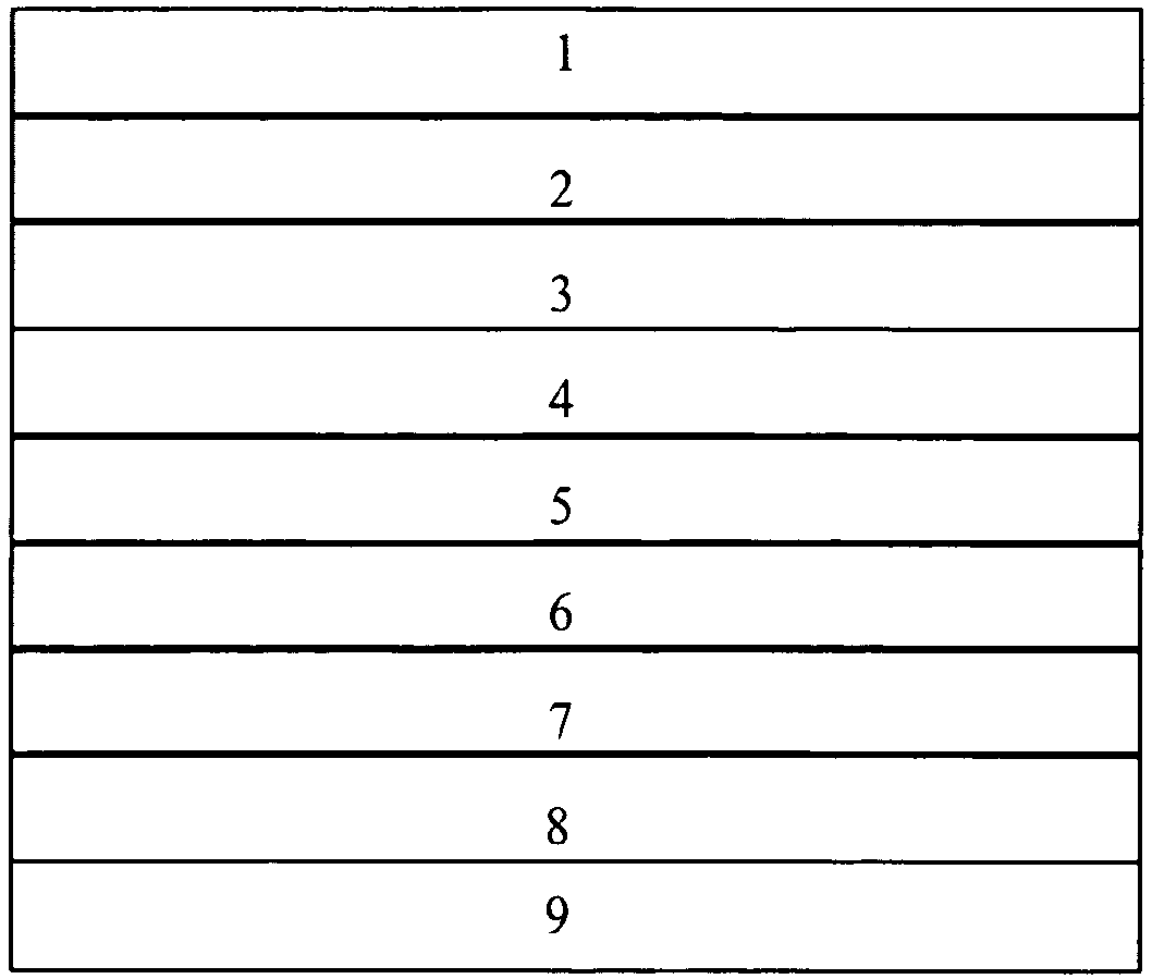
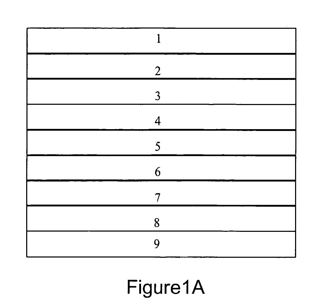
[0190]An exemplary dense multilayer membrane useful for hydrogen separation or purification at a preferred temperature range of 300 to 600° C. with layers as illustrated in FIG. 1A is prepared with layers and layer thicknesses as follows:[0191]Layer 1: porous alumina, 1 mm thick;[0192]Layer 2: porous zinc oxide, 1 mm thick;[0193]Layer 3: Pd, 0.25 μm thick;[0194]Layer 4: 60 vol. % RbNO3 / 40 vol. % La1-xSrxCoO3 (LSC, where 0.1≦x≦0.4), 1 μm thick;[0195]Layer 5: Vanadium metal, 100 μm thick;[0196]Layer 6: same as Layer 4;[0197]Layer 7: same as Layer 3;[0198]Layer 8: none; and[0199]Layer 9: none.


PUM

PropertyMeasurementUnit
Temperatureaaaaaaaaaa
Digital informationaaaaaaaaaa

Abstract

This invention provides hydrogen-permeable membranes for separation of hydrogen from hydrogen-containing gases. The membranes are multi-layer having a central hydrogen-permeable layer with one or more catalyst layers, barrier layers, and / or protective layers. The invention also relates to membrane reactors employing the hydrogen-permeable membranes of the invention and to methods for separation of hydrogen from a hydrogen-containing gas using the membranes and reactors. The reactors of this invention can be combined with additional reactor systems for direct use of the separated hydrogen.

Description

CROSS-REFERENCE TO RELATED APPLICATIONS[0001]This application takes priority under 35 U.S.C. 119(e) from U.S. provisional application Ser. No. 60 / 502,158, filed Sep. 10, 2003. This application is a continuation-in-part of U.S. patent application Ser. No. 10 / 382,354, filed Mar. 5, 2003, now U.S. Pat. No. 6,899,744 which in turn takes priority from U.S. provisional application 60 / 362,167, filed Mar. 5, 2002. Each of these applications is incorporated by reference herein to the extent that it is not inconsistent with the disclosure herein.STATEMENT REGARDING FEDERALLY FUNDED RESEARCH[0002]This invention was made with United States government funding though the Department of Energy National Energy Technology Laboratory Contract No. DE-FC26-00NT40762. The United States government has certain rights in this invention.BACKGROUND OF THE INVENTION[0003]The present invention relates to hydrogen-permeable membranes, which separate hydrogen from mixtures of gases by allowing selective diffusion...

Claims


Application Information

Patent Timeline
IPC IPC(8): B01D53/22B01D71/02B01D69/10B01D69/12B01D69/14B01J19/24B01J23/00B01J35/06C01B3/16C01B3/50C04B35/01C04B35/04C04B35/117C04B35/26C04B35/42C04B35/443C04B35/46C04B35/468C04B35/47C04B35/488
CPCB01D53/228C22C29/12B01D69/12B01D69/141B01D71/02B01D71/022B01D71/024B01J19/2475B01J35/065B22F7/02C01B3/16C01B3/503C01B3/505C04B35/01C04B35/016C04B35/04C04B35/117C04B35/2675C04B35/2683C04B35/42C04B35/44C04B35/443C04B35/46C04B35/4682C04B35/47C04B35/488C04B35/50C04B35/505B01D69/10B01D2325/26B01J23/002C01B2203/0283C01B2203/041C01B2203/047C01B2203/0475C01B2203/048C01B2203/0485C01B2203/1041C04B2235/3205C04B2235/3213C04B2235/3215C04B2235/3224C04B2235/3227C04B2235/3229C04B2235/3241C04B2235/3268C04B2235/3272C04B2235/3275C04B2235/3277C04B2235/3279C04B2235/405C04B2235/762C04B2235/768C04B2235/80Y02P20/52B01J35/59B01D71/0213B01D71/02232B01D71/0271
Inventor ROARK, SHANE E.MACKAY, RICHARDMUNDSCHAU, MICHAEL V.
Owner ELTRON RES
Learn More