However, when fluid drives experience fault conditions that stop the output shaft, that is, rotation of the output shaft and the attached runner ceases, it is very likely that the oil within the fluid drive
impeller and runner chamber as well as the
impeller, runner, and
impeller casing will experience much higher temperatures, on the order of 300 degrees F., sometimes up to 450 degrees F., and the rise in temperature will be experienced extremely rapidly after the
initiation of such a fault.
Almost always, a fault of this type occurs in the equipment driven by the fluid drive, examples being (1) a pump for which the supply of the liquid being pumped stops, and the pump overheats and freezes, so that the pump shaft can not rotate, and any shafting connected to it including a fluid drive can not rotate; and (2) a
hammer mill that becomes jammed, and can no longer rotate.
Such high temperatures, particularly when they occur rapidly, can damage the components of the fluid drive rotating elements, bearings, surrounding housings, the oil, the oil conditioning
system, oil pumps, and seals.
When the paint on the fluid drive, oil pipes,
heat exchanger, and pumps is discolored and peels off, almost always, severe damage has occurred to the internal components.
The heating occurs when the fluid drive impeller and runner cavities are filled, or partially filled, with oil and the impeller continues to rotate while the runner stops, causing power to be dissipated in the oil within the fluid drive element which is many times the
power loss dissipated in the oil during normal operation, with the obvious consequence that the
oil temperature rapidly soars to the aforementioned excessive temperatures.
The
instrumentation may be severely damaged by the event and the damage may not be detected because such events are rare and there is little experience with the damage such over-heating events can do.
One example of such damage is this: A Bourdon tube based device can be damaged by an over-temperature event because the fluid expands more than is anticipated and will cause some portion of the
bulb or measuring
capsule to expand and yield, causing the instrument to have an offset in its measuring and switching capability.
A problem occurs when the instrument is calibrated in a
test room at 70 degrees F., and the instrument is mounted on a fluid drive the temperature of which varies substantially.
Self contained sensor and switch units, such as produced under the name of Kaiser have been found to be damaged and non-functional after over-temperature events with temperatures over 450 degrees F., confirming prior experience that instruments containing switches that were mounted on the side of fluid drives did not work properly when exposed to high temperature conditions.
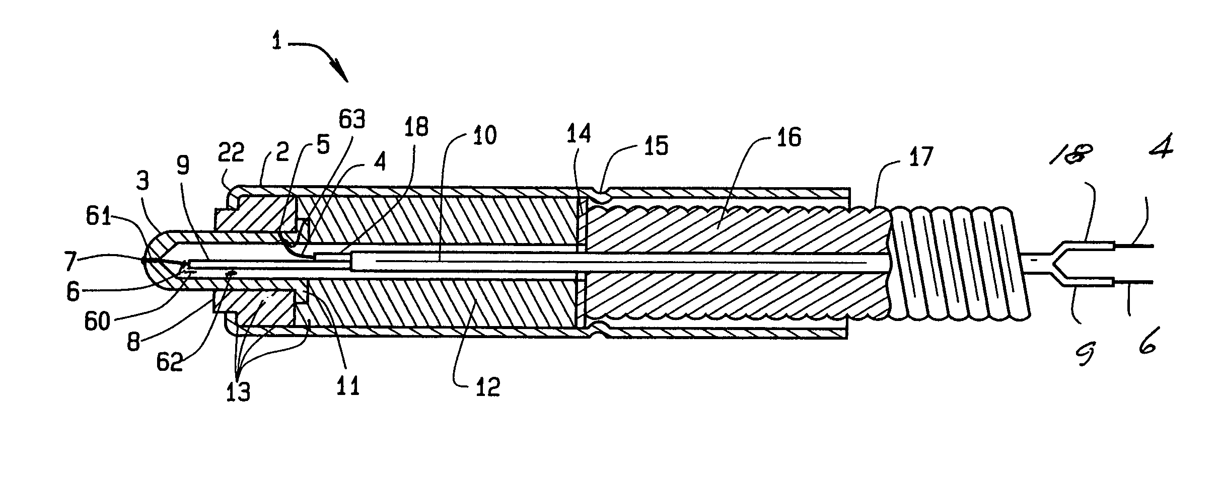
The layer of insulation used in ungrounded thermocouples as described just above provides a
delay in
heat transfer from the outer protective sheath or tube to the thermocouple junction, hence, ungrounded thermocouples so designed do not qualify as fast acting thermocouples.
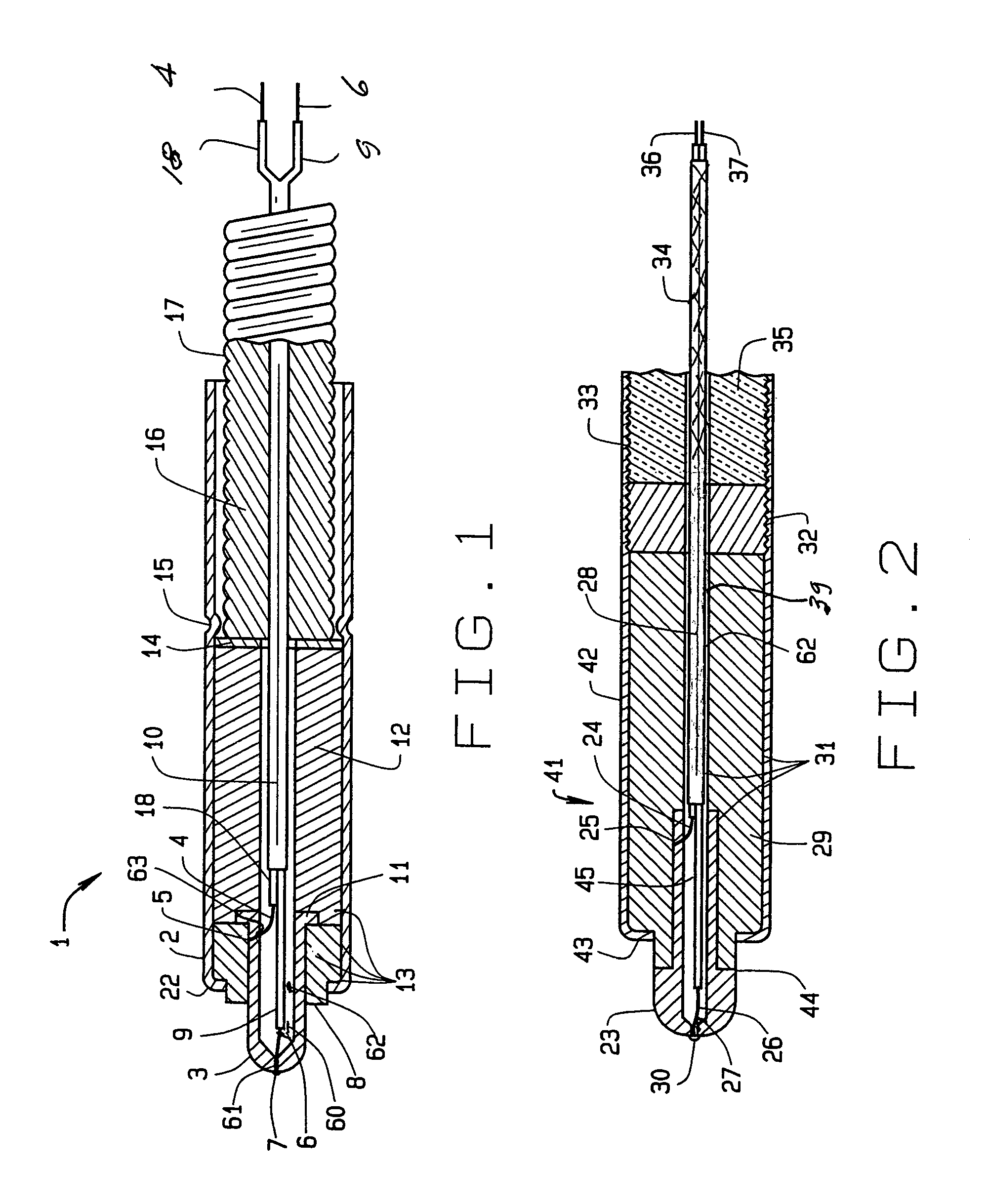
However, occasionally, the pressures of the lubricating
oil film on the
Babbitt layer, and hence, on the flat disc at the end of the thermocouple cause the flat disc to
dimple inwardly.
Sometimes, the pressures are so great that the end of the thermocouple is pushed into the hole and the sensor is destroyed.
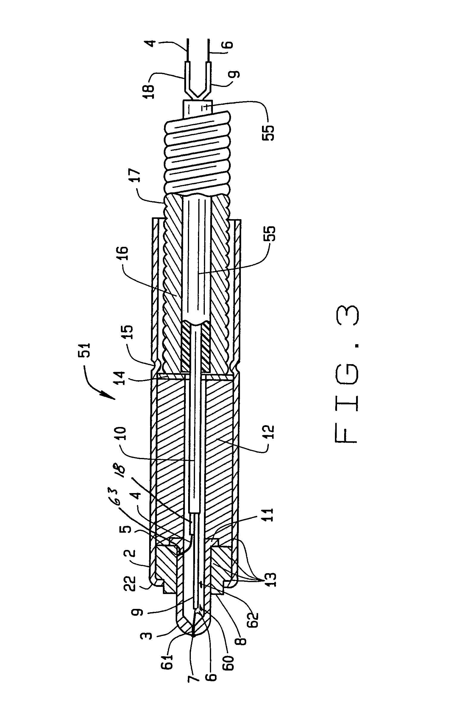
A problem that often occurs with grounded instrumentation, including thermocouples, sometimes unknown to the designer or user, is that other
electrical equipment in the area can induce stray voltages into the instrumentation, such stray voltages being either
direct current and / or
alternating current.
Occasionally these stray currents are traced to such conditions as improper grounds or loose ground wires.


