Method and apparatus for composite YAG laser/arc welding

a composite yag laser and arc welding technology, applied in the direction of welding apparatus, manufacturing tools, welding/cutting media/materials, etc., can solve the problems of severe demand, preventing the attainment of satisfactory bonding strength, and defects in welding, so as to increase the width of fusion and increase the depth of fusion. , the effect of high efficiency

Inactive Publication Date: 2006-03-07
HONDA MOTOR CO LTD
View PDF16 Cites 12 Cited by
  • Summary
  • Abstract
  • Description
  • Claims
  • Application Information

AI Technical Summary

Benefits of technology

[0019]It is an object of the invention to perform a welding operation with an increased width of fusion and an increased depth of fusion at a high efficiency.
[0020]The present invention relates to a composite YAG laser welding method in which an arc electrode is disposed close to a machining head of a YAG laser (or laser radiation condenser system) with a potential applied between the electrode and the member being welded so that the welding operation takes place thorough a combination of the YAG laser and the electric arc. According to the composite YAG laser welding method, the irradiation with the YAG laser radiation produce dissociated gasses and vapors of weld metal which are effective to excite and maintain an arc between the arc electrode and the member being welded and an atmosphere (plume) comprising plasmoid gasses and vapors of weld metal is maintained as close to a region which is irradiated by the laser by the combination of the YAG laser radiation and the arc.
[0021]Specifically, according to the composite YAG laser / arc welding method of the present invention, a spot on a member being welded which is irradiated by the YAG laser is targeted by the arc electrode, and while an arc power supply is connected across the arc electrode and the member being welded, the member being welded is irradiated by the YAG laser to produce plasmoid gasses and metal vapors which are effective to start an arc from the arc electrode, thus maintaining the plasmoid gasses and metal vapors which are produced by the YAG laser within and without the keyhole, thus completing the combined YAG laser / arc welding operation.
[0022]In a normal TIG process, a high frequency spark is created between the electrode and member to dissociate gasses in order to produce an arc. However, according to the present invention, there is no need to create such a high frequency spark. The plume, that is, the plasmoid gasses and metal vapors which are produced by the YAG laser and the arc assume an elevated temperature and a high pressure to depress a molten metal, and such heat transfer achieves a welding rate and a bead width which are greater than those achieved by the laser alone, thus allowing a greater depth of fusion.
[0023]This allows an increase in the gap margin in the butt welding operation, an increase in the width of faying interface in the lap welding operation, and an increase in the width of fusion in the fillet welding operation to be obtained, securing a bonding strength and providing a stable performance which is free from weld defects.
[0024]It will also be noted that when the invention is applied in the welding operation in which the filler wire is concurrently supplied, the heat input from the arc contributes to melting the filler wire, thus preventing the weldability from being degraded. It will be noted that the heat input from the arc generated allows a YAG laser of a low output to achieve a welding performance which is comparable to a YAG laser of a greater output. It is a simple matter to split a laser radiation from a single YAG laser source to a plurality of laser irradiation heads, thus allowing the installation cost per laser irradiation head to be simply reduced.

Problems solved by technology

1) YAG laser is used in the welding operation by condensing the beam radiation to achieve an increased power density. However, the condensed spot has a very small diameter on the order of φ0.3 to φ0.1 mm, and this causes the following inconveniences;
For butt welding, the presence of a gap between members to be welded which are disposed in abutment against each other (see FIG. 4a, for example) allows the laser radiation to pass through the gap, causing weld defects.
This imposes a severe demand on the cutting of an end face of a member to be welded where a weld is to be formed as well as on the manner of constraining parts of the members located adjacent to the weld.
For lap welding, the width of faying interface of a bead which extends from a top member to a bottom member (see FIG. 4b, for example) is limited, preventing a satisfactory bonding strength from being obtained.
For fillet welding, a satisfactory depth of fusion (see FIG. 4c. for example) cannot be obtained in the similar manner as mentioned above, preventing a satisfactory bonding strength from being obtained.
Where a filler wire is concurrently supplied to a region subject to YAG laser welding for purpose of improving excess weld metal or surface bead, the weldability is degraded because the power is consumed in melting the filler wire.
2) YAG laser apparatus requires a high equipment cost or initial cost, and therefore, where a plurality of equipment must be provided as in an automobile production line, a prohibitive installation cost results.
However, it will be seen that only the fusion produced by the laser prevails at a deep position, limiting the width of the fusion and resulting in a reduced welded strength.

Method used


Image

  • Method and apparatus for composite YAG laser/arc welding
  • Method and apparatus for composite YAG laser/arc welding
  • Method and apparatus for composite YAG laser/arc welding

Examples


first embodiment

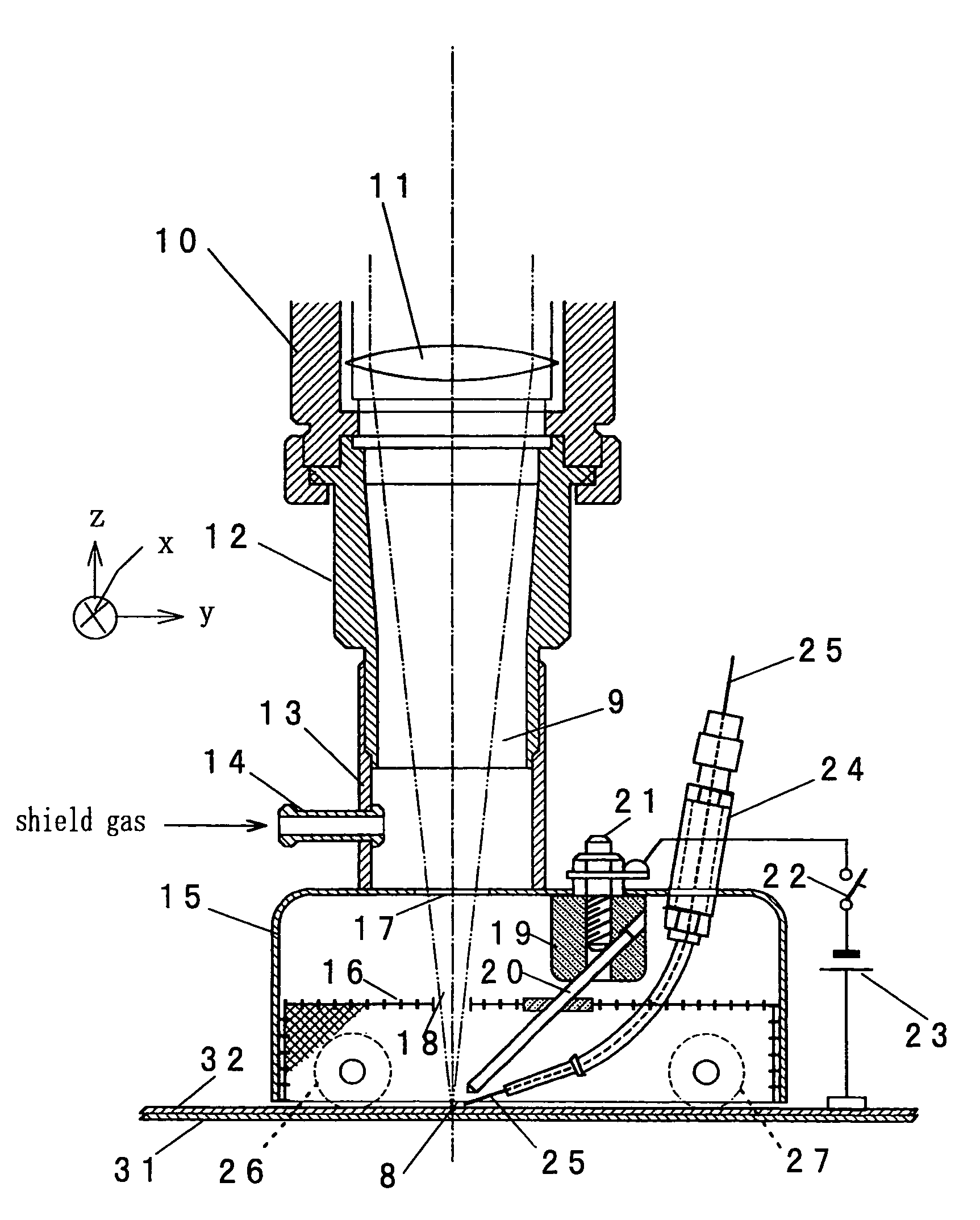
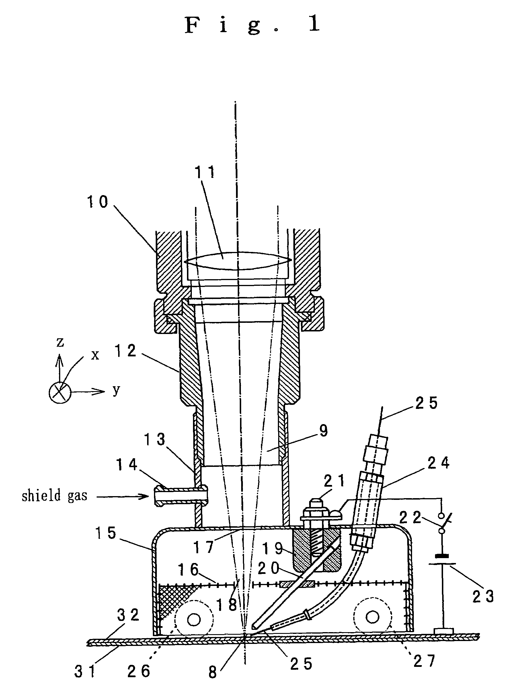
[0034]FIG. 1 shows a composite YAG laser / arc welding apparatus according to one embodiment of the present invention. YAG laser beam 9 is supplied from a YAG laser source, not shown, through an optical fiber cable, not shown, to a YAG irradiation head 10. The head 10 includes a lens 11 through which the laser radiation is passed to converge to a focus 8 (a point being irradiated) through an objective sleeve 12 and a relay sleeve 13.

[0035]An objective hood 15 is secured to the bottom of the relay sleeve 13. A gas commutation metal network 16 is disposed within the hood 15 to divide the interior of the hood into an upper space or a gas supply space and a lower space or welding space. The hood 15 and the metal network 16 are formed with openings 17 and 18, respectively, which allow the laser radiation 9 to be directed toward the focus 8.

[0036]An electrode base 19 formed of ceramics is secured to the hood 15, and a tungsten electrode 20 is mounted on the electrode base 19 and is oriented...

second embodiment

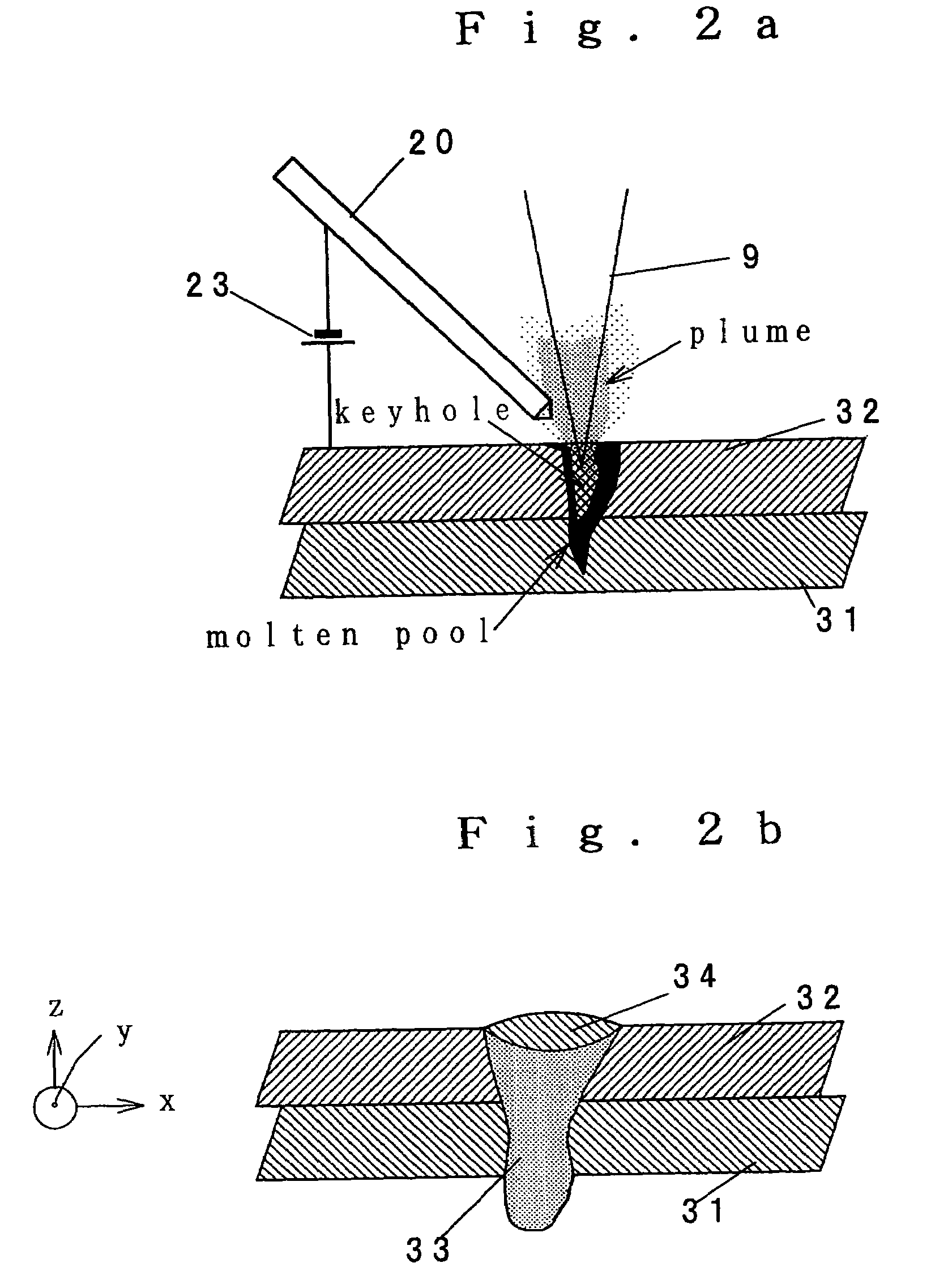
[0053]FIG. 3a shows a composite YAG laser / arc welding apparatus according to a second embodiment. In the second embodiment, there is no filler wire feeding, and thus the wire guide 24 of the composite welding apparatus of the first embodiment is omitted. In this embodiment, because no power is dissipated in melting the filler wire, the arc current is reduced. As a consequence, a lap welding bead as shown in FIG. 3b is obtained. Again, the width of faying interface is large and the fusion is deep. A high rate welding operation with a stabilized quality is possible. Welding conditions used are given below.[0054]Welded member 31: material A5052, 2 mm thick[0055]Welded member 32: material A5052, 2 mm thick[0056]YAG laser: output 4 KW, without assist gas (center gas)[0057]Arc

[0058]Current: 150 A

[0059]Tungsten electrode: 2.4 mm in diameter[0060]Shield gas: Ar 25 liters / min[0061]Welding rate: 4 m / min

[0062]As described above, since the plume generated by the laser irradiation starts an elec...


PUM


Abstract

A combined YAG laser / arc welding apparatus performs a welding operation with a large depth of fusion and a deep fusion at a high efficiency. The welding apparatus includes an arc electrode which targets a point on a member being welded where a laser beam from a YAG laser is focused. While an arc power supply is connected between the arc electrode and the member being welded, the member being welded is irradiated by the YAG laser to produce plasmoid gasses and metal vapors or a plume which is effective to start an arc from the arc electrode. A combined YAG laser / arc welding operation takes place while keeping the plume within and without a keyhole. Welded surface is covered by a hood, and a shielded gas passed through a commutation metal network surrounds the welded focus to prevent an oxidation and keeps the plume maintained. A filler wire is fed to a molten pool.

Description

[0001]This is a Divisional of application Ser. No. 10 / 318,032, filed on Dec. 13, 2002.[0002]The disclosure of the prior application is hereby incorporated by reference herein in its entirety.FIELD OF THE INVENTION[0003]The present invention relates to the art of YAG laser welding in which the input welding heat is assisted by an electric arc, or a welding method utilizing a combination of YAG laser and an electric arc and an apparatus therefor.BACKGROUND OF THE INVENTION[0004]YAG laser welding has features as mentioned below and is extensively used in the automatic welding process for automobiles.[0005]1) A focused laser radiation is obtained and enables a welding operation with a low distortion and at a high rate;[0006]2) Laser radiation absorption coefficient for metal materials is several times higher than for a CO2 laser, thus allowing an efficient welding operation. Since the wavelength of the laser radiation is on the order of 1 / 10 that of CO2 laser, attenuation caused by plas...

Claims


Application Information

Patent Timeline
Patent Type & Authority Patents(United States)
IPC IPC(8): B23K26/00B23K26/12B23K9/16B23K26/21B23K26/346
CPCB23K26/1429B23K26/348
Inventor SONODA, HIROFUMIOKUYAMA, KENJIIBUKURO, JUNICHIYAHABA, TAKANORITAKIKAWA, MASATOICHIYAMA, YASUTOMOUKENA, TOSHIYASU
Owner HONDA MOTOR CO LTD
Why Eureka
Try Eureka