Method for the manufacture of phase shifting masks for EUV lithography

a technology of euv lithography and manufacturing method, which is applied in the direction of relative volume flow measurement, photomechanical apparatus, instruments, etc., can solve the problems of incompatibility of euv mask technology and the technology for producing phase shift in the duv mask, and the manufacture of sharp phase gradients and phase discontinuities is difficult, so as to reduce the required numerical aperture, enhance the printability of the reflection mask, and reduce the effect of the required apertur

Inactive Publication Date: 2006-04-04
EUV +1
View PDF4 Cites 4 Cited by
  • Summary
  • Abstract
  • Description
  • Claims
  • Application Information

AI Technical Summary

Benefits of technology

[0024]The invention is a phase shifting mask and a method for fabricating a phase shifting mask for EUV lithography. The principle is to enhance the printability of a reflection mask consisting of a patterned absorber layer deposited on a reflective multilayer coating by producing a phase shift between the fields reflected on either side of a critical feature, as shown in FIG. 4. A multilayer stack 40 on a substrate 42 includes a patterned absorber layer 44. Layer contraction is produced, e.g., at 46 by localized heating.
[0025]The strategy of applying a pi phase shift across a critical feature reduces k1 and extends the resolution of the imaging process well beyond the Raleigh diffraction limit. Other potential advantages derived from using the phase shift strategy include (1) reducing the required numerical aperture, which increases the depth of focus and decreases the manufacturing cost of the optical system, and (2) increasing the NILS of the aerial image, which increases the process latitude and makes the exposure less sensitive to flare. However, the methods used to produce phase shifting masks in DUV lithography do not readily extend to EUV lithography due to the fundamental change from the transmission to the reflection mode of operation. This invention consists of a process for producing a spatially varying phase shift in a EUV mask by locally modifying the structure of the reflective multilayer coating. The multilayer structure is modified by exposing the mask to a high-resolution thermal source such as an electron beam. The energetic beam causes thermally activated interdiffusion in the reflective multilayer coating, producing a contraction of the layers that results in a local phase shift with no appreciable loss of reflectivity. This process can be applied to the mask as a last step, after the patterning of the absorber layer, which has the advantage of being able to use the absorber pattern for alignment.

Problems solved by technology

Although the concept of a phase shifting mask can be directly extended to EUV lithography, the existing technologies for making DUV phase shifting masks are not compatible with EUV mask technology.
This is fundamentally different from the transmissive masks currently used in DUV lithography, and the technology for producing phase shifts in the DUV masks cannot be directly applied to reflective EUV masks.
A major drawback of this technique is that it requires patterning of the mask blank prior to deposition of the reflective multilayer, which would require the multilayer coating infrastructure to be incorporated into the patterning process line.
Furthermore, the smoothing process which takes place during multilayer deposition, and which is used to reduce the printability of substrate defects, would make the manufacture of sharp phase gradients and phase discontinuities difficult.
The problem is that at EUV wavelengths the optical constants are not as forgiving as for visible light For example, a 43 nm thick layer of Molybdenum will impart a π phase shift on reflected 13.4 nm light, but will also reduce the reflected intensity by a factor of 0.6.
Such localized loss of intensity associated with the production of the phase shift is not good when the aim is to produce a purely phase shifting mask, and could cause serious limitations on the practical utility of this approach to phase shifting.
1. The phase shifting features would be high aspect ratio trenches. Take the case of dense 1:1 features having a minimum feature size of 20 nm at the wafer. For a 4× magnification optical system the feature size on the mask would be 80 nm. The phase shifting trenches would be etched between every other feature, and would need to be less than 80 nm wide and 100 nm deep. This would be difficult to achieve cleanly in the multilayer without damaging the layers or getting undesired edge effects from the finite resolution of the ion mill.
2. The interaction of the radiation with the phase shifting features would be complicated, and would certainly include some diffraction from the side walls. This could lead to undesirable modulations of the aerial image that would be difficult to control.

Method used


Image

  • Method for the manufacture of phase shifting masks for EUV lithography
  • Method for the manufacture of phase shifting masks for EUV lithography
  • Method for the manufacture of phase shifting masks for EUV lithography

Examples


Embodiment Construction

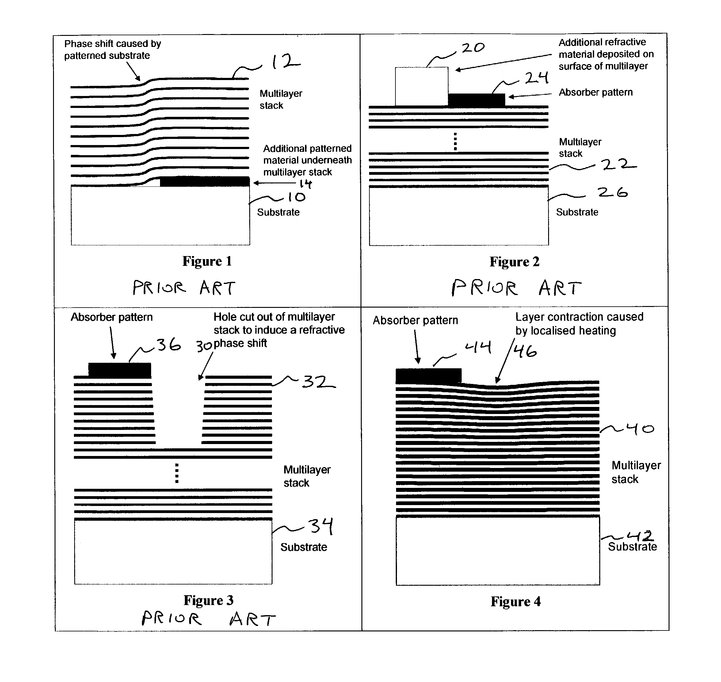
[0033]The invention described herein is compatible with the manufacture of phase shifting reflective EUV masks in which all steps can be accomplished as a part of the patterning process. U.S. patent application Ser. No. 09 / 669,390, filed Sep. 26, 2000, titled “Repair Of Localized Defects In Multilayer-Coated Reticle Blanks For Extreme Ultraviolet Lithography” is incorporated herein by reference. U.S. patent application Ser. No. 09 / 752,887, titled “A Method For Fabricating Reticles For EUV Lithography Without The Use Of A Patterned Absorber” is incorporated herein by reference.

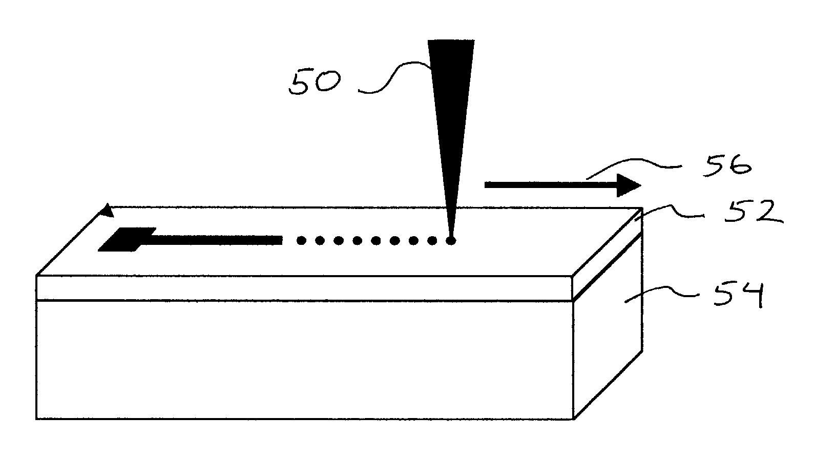
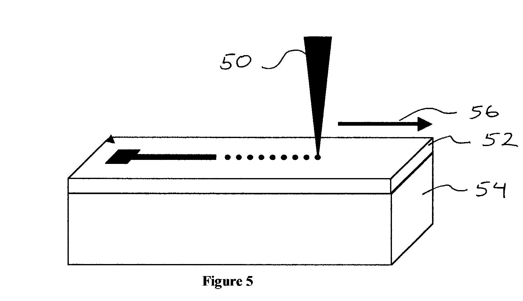
[0034]Embodiments of the present invention specifically contemplate the use of this technique on Mo / Si multilayers in which the heating is caused by a focused, energetic electron beam. However, the technique could be applied to multilayers made of other material, in which case the layer contraction described here could take the form of expansion. Furthermore, although the following description is directed to th...


PUM

PropertyMeasurementUnit
temperatureaaaaaaaaaa
thicknessaaaaaaaaaa
thicknessaaaaaaaaaa

Abstract

A method for fabricating an EUV phase shift mask is provided that includes a substrate upon which is deposited a thin film multilayer coating that has a complex-valued reflectance. An absorber layer or a buffer layer is attached onto the thin film multilayer, and the thickness of the thin film multilayer coating is altered to introduce a direct modulation in the complex-valued reflectance to produce phase shifting features.

Description

[0001]The United States Government has rights in this invention pursuant to Contract No. W-7405-ENG-48 between the United States Department of Energy and the University of California for the operation of Lawrence Livermore National Laboratory.BACKGROUND OF THE INVENTION[0002]1. Field of the Invention[0003]The present invention relates to the production of phase shifting masks for extreme ultraviolet lithography (EUVL), and more specifically, it relates to systems and methods for directly writing patterns into the reflective multilayer coating of an extreme ultraviolet lithography phase shifting mask and providing a patterned absorber layer onto the EUVL mask.[0004]2. Description of Related Art[0005]Phase shifting masks (also known as reticles) are commonly used as a resolution enhancement technique in optical lithography and the technology is well established and widely used in deep ultra-violet lithography systems. See U.S. Pat. No. 5,045,417, Okamoto et al., titled “Mask For Manuf...

Claims


Application Information

Patent Timeline
Patent Type & Authority Patents(United States)
IPC IPC(8): G01F9/00G03F1/24G03F1/30G03F7/20
CPCB82Y10/00B82Y40/00G03F7/70283G03F1/30G03F1/24
Inventor STEARNS, DANIEL G.SWEENEY, DONALD W.MIRKARIMI, PAUL B.BARTY, ANTON
Owner EUV
Why Eureka
Try Eureka