Ultraviolet laser apparatus and exposure apparatus using same

a laser and ultraviolet light technology, applied in the field of laser equipment, can solve the problems of difficult to correct chromatic aberration, limited application patterns, limited material used for forming lenses of exposure equipment, etc., and achieves the effects of low spatial coherence, easy maintenance, and high degree of freedom in the arrangement of parts

Inactive Publication Date: 2006-04-04
NIKON CORP
View PDF21 Cites 868 Cited by
  • Summary
  • Abstract
  • Description
  • Claims
  • Application Information

AI Technical Summary

Benefits of technology

[0042]As mentioned above, according to the present invention, since the light having single wavelength from the laser generating portion is amplified by the optical amplifier in the light source and the amplified light is converted into the ultraviolet light by the non-linear optical crystal of the wavelength converting portion, the ultraviolet light having the desired spectrum line width (for example, 1 pm or less) can easily be obtained without complicated arrangement.
[0043]Further, since the laser light having single wavelength is divided (or multiplexed) into the plurality of output lights and the plural output lights are amplified by

Problems solved by technology

However, they had disadvantage that applicable patterns were limited.
In a second condition, in case of ultraviolet light having a wavelength smaller than 300 nm, material used for forming a lens of the exposure apparatus is limited, and it is difficult to correct chromatic aberration.
Therefore, if light having a narrow line width is emitted as it is, an undesired interference pattern called as speckle will be generated.
However, these excimer lasers have several disadvantages that they are bulky, that optical parts are apt to be damaged because of great energy per one pulse and that maintenance of the laser is troublesome and expensive because of usage of harmful fluorogas.
However, these methods have disadvantages that the adjustment is delicate and that, as the number of laser elements is increased, the arrangement for causing all of the laser elements to perform oscillation having the same wavelength becomes more complicated.
However, this method has a disadvanta

Method used


Image

  • Ultraviolet laser apparatus and exposure apparatus using same
  • Ultraviolet laser apparatus and exposure apparatus using same
  • Ultraviolet laser apparatus and exposure apparatus using same

Examples


first embodiment

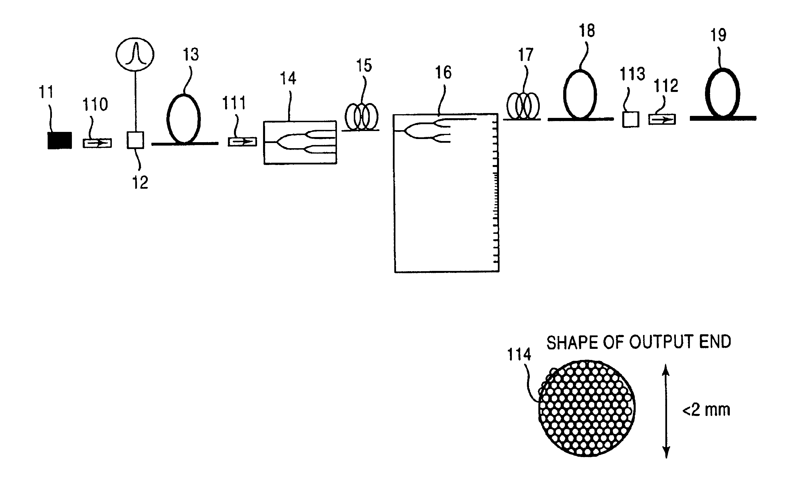
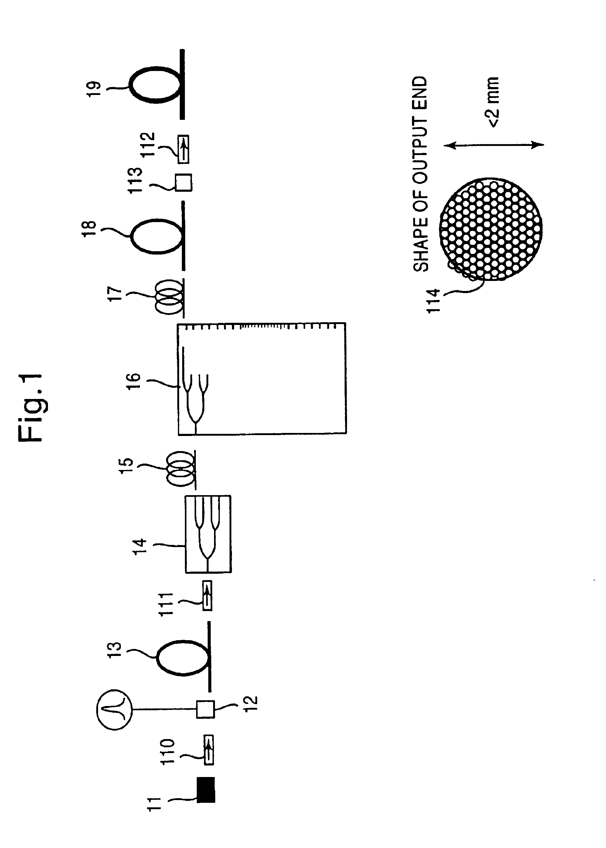
[0068]Now, the first embodiment will be fully explained. As the single wavelength oscillating laser 11 for generating the laser beam having a single wavelength for example, InGaAsP, DFB semiconductor laser having an oscillating wavelength of 1.544 μm and continuous wave output (referred to as “CW output” hereinafter) of 20 mW. The DFB semiconductor laser is designed so that, in place of a Fabry-Perot resonator having low longitudinal mode selection, diffraction gratings are incorporated into a semiconductor laser to perform single longitudinal mode oscillation under any conditions and is called as a distributed feedback (DFB) laser. In such a laser, since single longitudinal mode oscillation is effected fundamentally, a line width of an oscillation spectrum can be suppressed below 0.01 pm.

[0069]Further, in order to fix the output wavelength of the ultraviolet laser apparatus to a given wavelength, it is preferable to provide an oscillating wavelength controlling device for controlli...

second embodiment

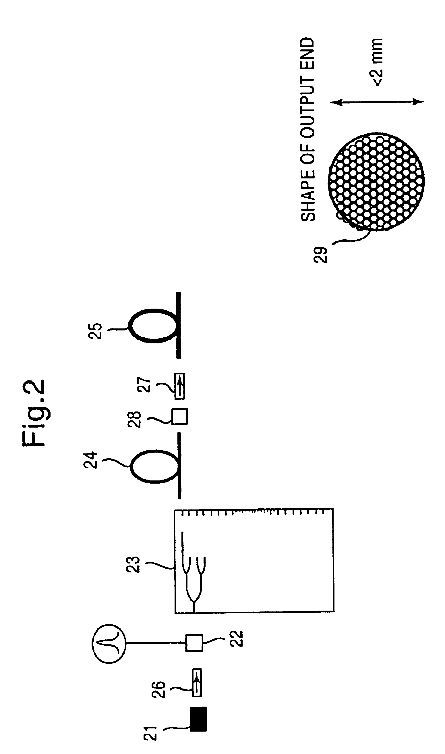
[0090]Now, the second embodiment will be fully described. As the single wavelength oscillating laser 21 for generating the laser beam having a single wavelength, for example, an ytterbium (Yb) doped fiber laser or a DFB semiconductor laser having an oscillating wavelength of 1.099 μm and CW output of 20 mW is used. In such lasers, since single longitudinal mode oscillation is effected fundamentally, a line width of an oscillation spectrum can be suppressed to less than 0.01 pm.

[0091]The light output (CW light) of this semiconductor laser is converted into pulse light, for example, by using a light modulating element 22 such as an electro-optical light modulating element or an acousto-optical light modulating element. In the illustrated embodiment, as an example, a case where the output is modulated to pulse light having pulse width of 1 ns and repetition frequency of 12.8 MHz (pulse period of 78 μs) will be explained. As a result of such light modulation, a peak power of the pulse l...

third embodiment

[0125]Now, the third embodiment will be fully explained. As the single wavelength oscillating laser 31 (FIG. 3) for generating the laser beam having a single wavelength, for example, InGaAsP, DFB semiconductor laser having an oscillating wavelength of 1.544 μm and CW output of 30 mW is used. In this laser, since single longitudinal mode oscillation is effected fundamentally, an oscillation spectrum line width can be suppressed below 0.01 pm.

[0126]The light output (continuous light) of the semiconductor laser 31 is converted into pulse light, for example, by using a light modulating element 32 such as an electro-optical light modulating element or an acousto-optical light modulating element. In the illustrated embodiment, as an example, a case where the output is modulated to pulse light having pulse width of 1 ns and repetition frequency of 100 kHz will be explained. As a result of such light modulation, peak power of the pulse light outputted from the light modulating element 32 be...


PUM


Abstract

An ultraviolet laser apparatus having a single-wavelength oscillating laser generating laser light between an infrared band and a visible band, an optical amplifier for amplifying the laser light, and a wavelength converting portion converting the amplified laser light into ultraviolet light using a non-linear optical crystal. An exposure apparatus transfers a pattern image of a mask onto a substrate and includes a light source having a laser apparatus emitting laser light having a single wavelength, a first fiber optical amplifier for amplifying the laser light, a light dividing device for dividing or branching the amplified laser light into plural lights, and second fiber optical amplifiers for amplifying the plural divided or branched lights, respectively, and a transmission optical system for transmitting the laser light emitted from the light source to the exposure apparatus.

Description

[0001]This application is a divisional of prior application Ser. No. 09 / 538,233 filed Mar. 30, 2000 now U.S. Pat. No. 6,590,698 which is a continuation PCT application of PCT / JP98 / 05367 filed on Nov. 30, 1998.BACKGROUND OF THE INVENTION[0002]1. Field of the Invention[0003]The present invention relates to a laser apparatus and more particularly it relates to an ultraviolet laser apparatus for generating ultraviolet light capable of suppressing generation of speckle with low coherence, such as an exposure light source used in a photo-lithography process for manufacturing micro devices such as semiconductor elements, liquid crystal display elements. CCD and thin film magnetic heads, as well as relates to an exposure apparatus using such an ultraviolet laser apparatus.[0004]2. Description of the Related Art[0005]As information technology equipment has progressed, regarding integrated circuits, improvement in function, memory capacity and compactness have been requested, and to achieve t...

Claims


Application Information

Patent Timeline
IPC IPC(8): G02F1/37G02F1/35H01S3/109G03F7/20H01S3/067H01S3/23
CPCG02B6/14H01S3/2383G02F1/1303G02F1/35G02F1/3501G02F1/353G03F7/70025G03F7/70575H01S3/067H01S3/06758G02B6/32G02F1/37G02F2001/3503G02F2001/354H01S3/005H01S3/0057H01S3/0064H01S3/0078H01S3/0085H01S3/06716H01S3/06729H01S3/06745H01S3/06766H01S3/094011H01S3/09415H01S3/1608H01S3/23G02F1/3503G02F1/354H01S3/109
Inventor OHTSUKI, TOMOKOOWA, SOICHI
Owner NIKON CORP
Why Eureka
Try Eureka