Chemical reactor

a chemical reactor and reactor technology, applied in the field of chemical engineering, can solve the problems of unwanted by-products and undesired effects, damage to the associated apparatus, and general adverse effects of endothermic reactions on the rate of reaction and the corresponding parameters, so as to achieve close control of the reactant temperature profile, avoid unwanted reactions, and reduce back mixing

Inactive Publication Date: 2006-04-25
MEGGIT (UK) LTD
View PDF29 Cites 46 Cited by
  • Summary
  • Abstract
  • Description
  • Claims
  • Application Information

AI Technical Summary

Benefits of technology

[0035]An advantage of the invention is that close control of the reactant temperature profile can be achieved, and the temperature profile may be adjusted between sequential reaction compartments so that the reaction conditions may be optimised with respect the changing reactant and product concentrations. Accurate temperature control avoids transient or localised overheating of reactants or products. This is of particular significance where one of the reactants is particularly heat-sensitive, and can be thermally degraded in the event of incomplete mixing. Further, by approximating a plug flow reactor, back mixing is substantially reduced, and unwanted reactions may be avoided. Hence the reaction conversion, yield, and product quality may be improved.
[0036]A further significant benefit of the invention is that thorough and uniform mixing is achieved without use of an agitator. This results in energy savings, and eliminates the cost of maintaining agitator bearings and shaft seals.
[0037]Also, by reducing the residence time required, the hold-up volume of reactants and products is very much reduced. Substantial improvements in process safety are achieved where the reactants or products are hazardous eg toxic or flammable.
[0038]Preferably, all the heat exchangers used in the reactor are panels that are entirely of the printed circuit heat exchanger type (PCHE). Typically in such an arrangement, the heat transfer dimensions are smaller than catalyst particle dimensions, ensuring that the temperature profiles inherent in heat transfer to fluids in passages are not significant relative to the catalyst particle size. Also, the dimensions of the heat transfer are relatively small in comparison to the bed depth, so that any passage-scale temperature profiles occupy only a very small proportion of the individual catalyst bed lengths, e.g. typically up to about 200 mm. This contrasts significantly with the prior art use of exchanger tubes of say 25 mm outer diameter, which essentially cause downstream wakes in the temperature profiles which are then necessarily of a scale that is significantly larger than the individual catalyst particles and extend across at least a significant proportion of each catalyst bed.
[0039]The catalyst may be of variable form, e.g. selected from spherical, cylindrical, hollow bodies, solid particles, expanded or porous solids, coated matrix catalyst or the like supported catalysts. Commonly particles of up to about 10 mm (major dimension) are contemplated.
[0040]Preferably, the potential for catalyst particles to enter the passages of the PCHE is restricted by provision of a screen ideally of a durable mesh capable of restraining particles of catalyst at operational temperatures.

Problems solved by technology

The cooling effects for endothermic reactions generally adversely affect the rate of reaction and the corresponding parameters such as conversion and selectivity of the products from the reaction.
The uncontrolled heating of exothermic reactions generally leads to damage to the associated apparatus as the temperature can rise to a very high level.
The reaction in such a case may become uncontrolled (so-called “run away reaction”) and lead to unwanted by-products and undesired effects, such as deactivation of a process catalyst.
Furthermore, whilst an ideal catalyst does not theoretically participate in a reaction in reality many catalysts become degraded or poisoned as the reaction progresses and on an industrial scale the costs associated with catalyst regeneration or replacement represent a significant burden.
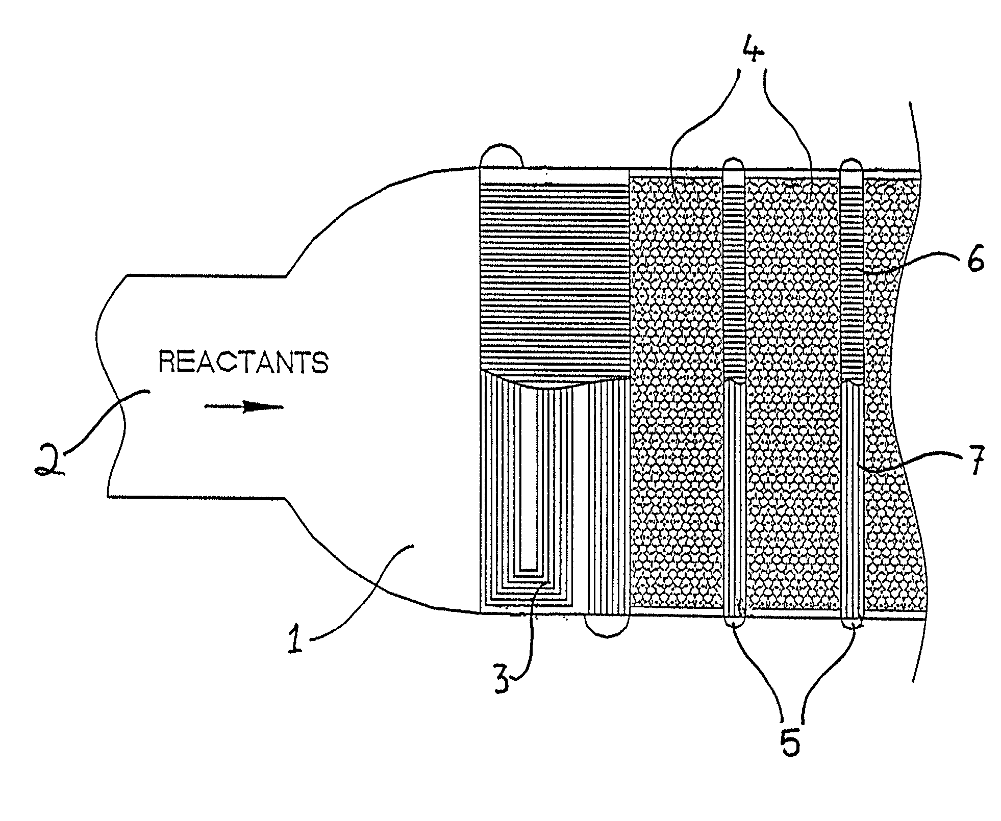
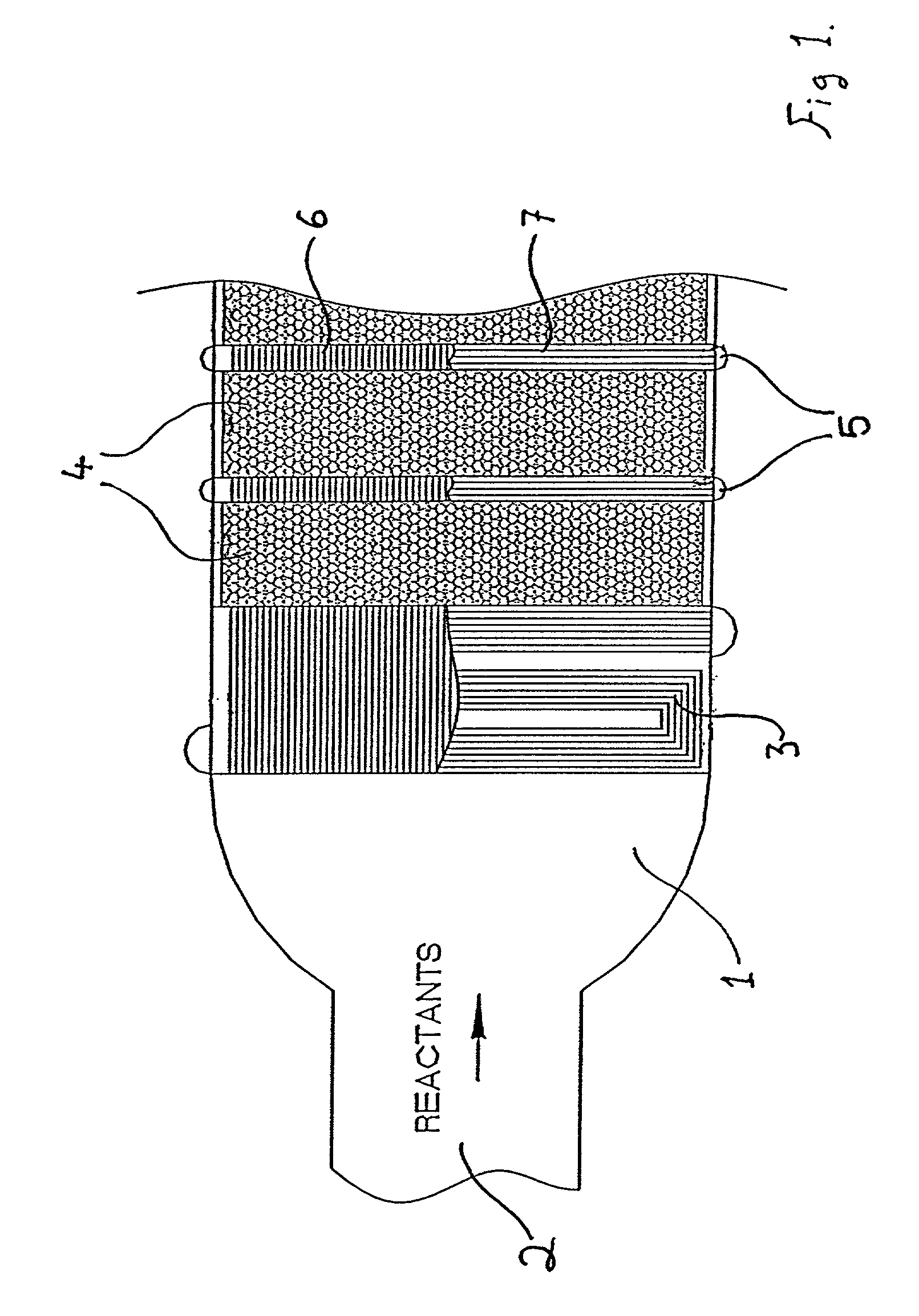
However, particularly for highly exothermic reactions, such an approach has not been found to be ideal since the packed bed often develops heat gradients, e.g. the catalyst bed will be cooler at its areas of contact with the said tubes or plates and hotter within its depth remote from said tubes or plates, permitting formation of hot spots or moving hot fronts leading to variations in reaction progress within the bed as a whole.
Typical approaches to such problems include the addition of quench gas to cool the system, but this leads to a loss in efficiency and may thus have an adverse effect on yield.
A further approach is to introduce a heat exchange step between adiabatic beds, which may involve the incorporation of heat exchangers into the reactor, but this leads to both design and operational problems due to the bulk of tubular designs and a lack of differential pressure containment with plate exchangers.
There are also problems with reactant re-distribution.
Alternatively, the reactants may be removed from the reactor for intermediate heat exchange e.g. cooling, but this also has an impact on plant design and process operation due to the additional expensive piping, and distribution problems with each extraction and re-injection.
Thus this is not practical to do more than once or twice in any particular system.
A further approach is to adopt continuous heat exchange by packing tubes or plates into the catalyst bed, but this leads to design inflexibility, additional expense, uneven packing of catalyst, and of course difficulty in replacing or regenerating the catalyst.
Alternatively, heat exchange tubes, plates and passages of the reactor may be coated with catalyst, but here again this leads to an inflexible design, difficulties in applying catalyst reliably and restrictions upon available superficial catalyst surface area.
Also with this approach, there are obvious difficulties in replacing or regenerating the catalyst.
Fluidised bed reactors represent another potential solution to these problems, but these may not be ideally suited to all or certain reaction systems.
The possibility of using an inert or reactive diluent to ballast the temperature of reactants in adiabatic beds has been considered but such a diluent must be heated, cooled, and pumped which places extra energy demands on the process and moreover, may also interfere with the intended reaction by presenting a diffusion barrier to reactants.
The plates are joined, such as by welding, along these smooth edges and hence the integrity of the seal of the channels formed by the corrugations in adjacent plates is not ideal, particularly where a large pressure differential exists between the heat exchange flow channels and the reaction flow channels since this will tend to urge the adjacent plates apart.
This arrangement will thus place unnecessary constraints on parameters of the reaction, namely the relationship between the pressure of the heat exchanging fluid and that of the reactant gas.
Thus there remains the possibility of hot spots and less than satisfactory thermal control in such large catalytic reactor volumes.
Unfortunately, both these parameters are process requirements and hence cannot be changed in order to improve the heat transfer coefficient in the packed bed, and hence in the reaction cells described in U.S. Pat. No. 5,073,352.
Additionally, it is difficult to move catalyst between narrow gaps or tubes, imposing limits on the dimensions of gaps or tubes through which catalyst is designed to flow.
Thus reactors of the known types according to the existing art have many significant limitations imposed on the heat transfer capability.
Generally both an external jacket and internal coil afford only a limited heat transfer surface.
External heat transfer requires pumped circulation, and imperfect mixing within the reactor can result in significant deviation between the composition of the fluid circulated through the external heat exchanger and bulk mixed fluid composition in the reactor.
This latter problem is most likely to arise whilst a reactant is being added to the reactor.
Efforts to ensure good mixing frequently meet with unsatisfactory results, and reaction conditions often need to be less than optimal to allow for variations in reactant concentration.
As a result of the shortcomings outlined above, some reactions are carried out with a reactor residence time that is much longer than needed by the reaction kinetics alone, due to poor heat and / or mass transfer, with consequent loss of reaction selectivity.
Further, CSTRs are characterised by substantially complete back mixing of reaction products with reactant; this can inhibit the reaction rate, and can also result in product loss through unwanted further reactions.

Method used


Image

  • Chemical reactor
  • Chemical reactor
  • Chemical reactor

Examples


Embodiment Construction

[0070]Referring to the drawings, FIG. 1 shows a reactor 1 provided with a reactant fluid inlet 2 and a reactant fluid outlet (not shown) through which a reactant fluid to be processed is passed.

[0071]The reactor 1 comprises at least one catalytic bed 4. Where the apparatus is configured as a moving bed reactor, the catalyst bed 4 is substantially vertical, to facilitate movement of the catalyst through the chamber.

[0072]Provided adjacent to the catalytic bed reactor 4 are printed circuit heat exchangers (PCHE) 5. The PCHEs 5 have at least two sets of channels formed therein, a first set of channels 6 provided for passage of the reactant fluid from a first catalytic bed 4 to a second, and a second set of channels 7 through which the heat exchanging fluid flows. The first of the PCHEs 5, in communication with the reactant fluid inlet 2, contains pre-heat channels 3. These pre-heat channels 3 are extra vertical passages in which heat exchanging fluid flows and heats the reactants to a ...


PUM

PropertyMeasurementUnit
thicknessaaaaaaaaaa
thicknessaaaaaaaaaa
thicknessaaaaaaaaaa

Abstract

A reactor comprises a reaction zone, optionally containing a catalyst bed, and heat exchange means inoperative contact with the reaction zone, e.g. embedded in a catalyst bed, and arranged so as to received reactants for heat exchange purposes, wherein the heat exchange means is formed from a plurality of superposed metal plates wherein fluid flow channels have been formed, according t a pre-determined pattern, the channel-bearing plates being aligned during superposition to define discrete heat exchange pathways respectively for reactant and working fluids, and the said plates are diffusion bonded together.

Description

CROSS-REFERENCE TO A RELATED APPLICATION[0001]This application claims priority under 35 U.S.C. §119(e) to U.S. Provisional Patent Application No. 60 / 184,007 entitled Catalytic Bed Reactor, filed Feb. 22, 2000, and under 35 USC §119(a) to G.B. 0001699.8, filed Jan. 25, 2000 and G.B. 0017187.6, filed Jul. 13, 2000, the entirety of each of which is incorporated herein by reference.FIELD OF THE INVENTION[0002]The present invention is applicable in the field of chemical engineering and especially relates to improvements in chemical reactors. In general the invention relates to process control of temperature in a chemical reaction system and processing plant. Particularly the invention provides a reactor suitable for rapid conversion of a fluid reactant within the reactor in which the reactant temperature is maintained at a desired profile indirectly by means of a heat exchanging fluid.BACKGROUND OF THE INVENTION[0003]In the majority of chemical processes there is a heat demand or a need ...

Claims


Application Information

Patent Timeline
Patent Type & Authority Patents(United States)
IPC IPC(8): F28F3/08B01J8/02B01J8/04B01J19/00C01C1/04
CPCB01J8/0221B01J8/0292B01J8/0438B01J8/0496B01J19/0013C01C1/0435B01J8/0285F28F2260/02B01J2208/0015B01J2208/00212B01J2208/00221B01J2219/00085B01J2219/182F28D9/0006F28D9/0031F28F3/048Y02P20/52
Inventor JOHNSTON, ANTHONYLEVY, WILLIAM
Owner MEGGIT (UK) LTD
Why Eureka
Try Eureka