
Tunable laser with a fixed and stable wavelength grid especially useful for WDM in fiber optic communication systems

a fiber optic communication system and wavelength grid technology, applied in the direction of lasers, laser optical resonators, angle demodulation, etc., can solve the problems of limited dynamic change ability, large discrepancies, and insufficient development, and achieve high reflection (hr) coating and effectively modulate the gain curve of the semiconductor amplifier

Inactive Publication Date: 2006-05-16
MRV COMM LTD 50
View PDF6 Cites 11 Cited by
  • Summary
  • Abstract
  • Description
  • Claims
  • Application Information

AI Technical Summary

Benefits of technology

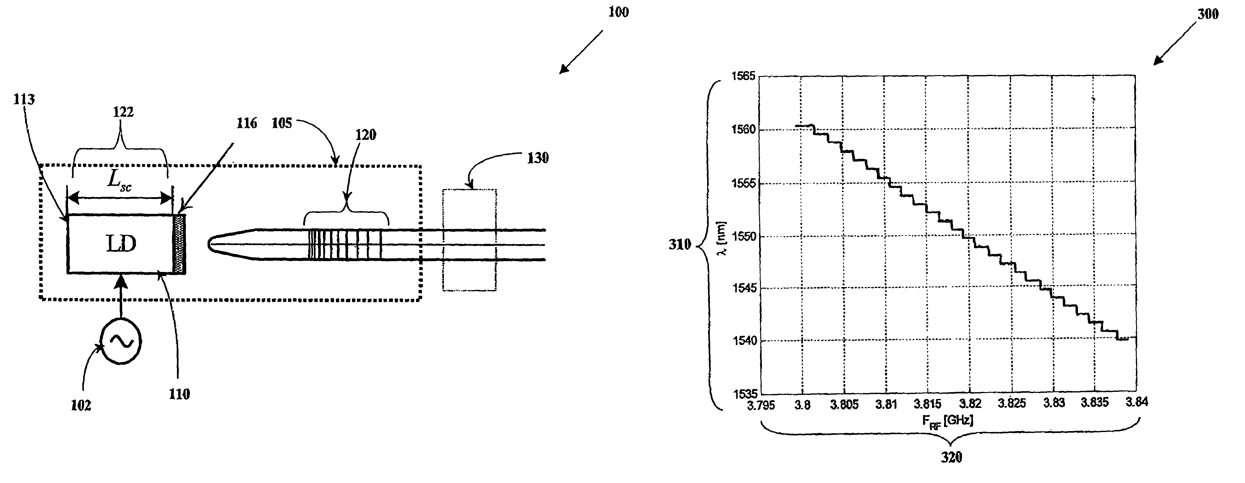
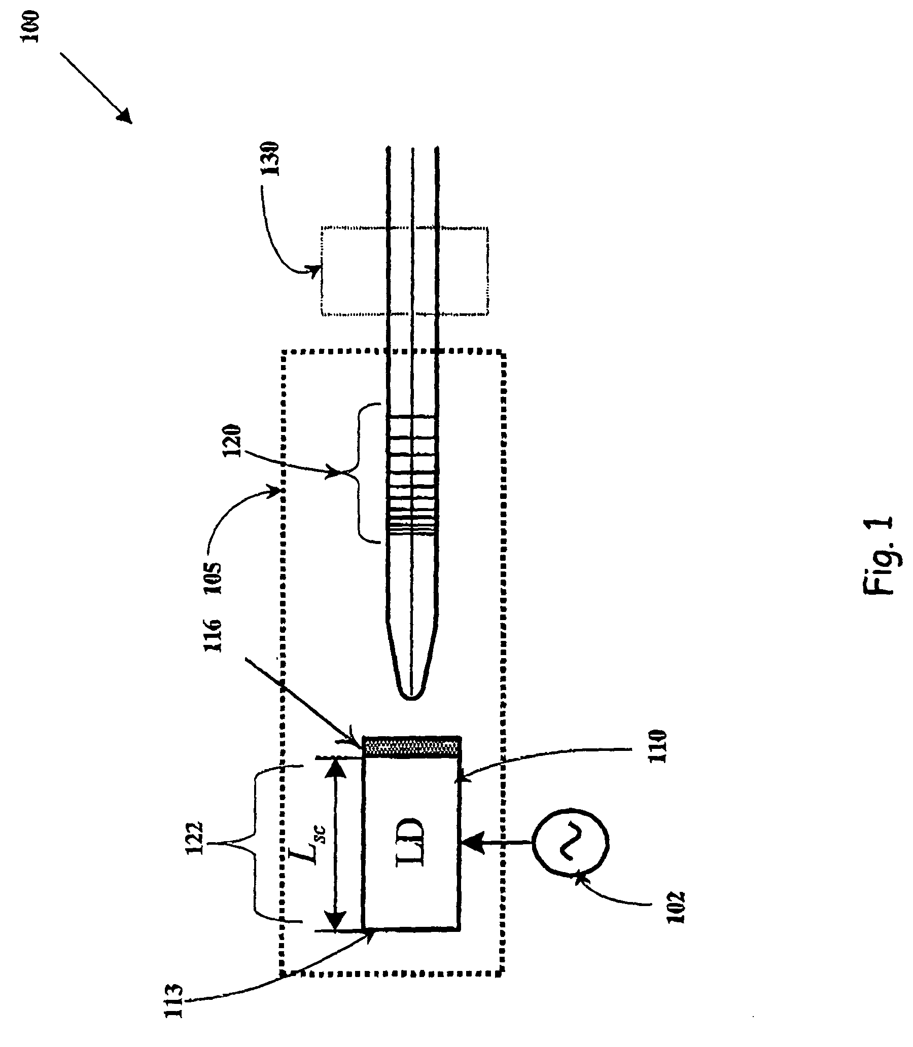
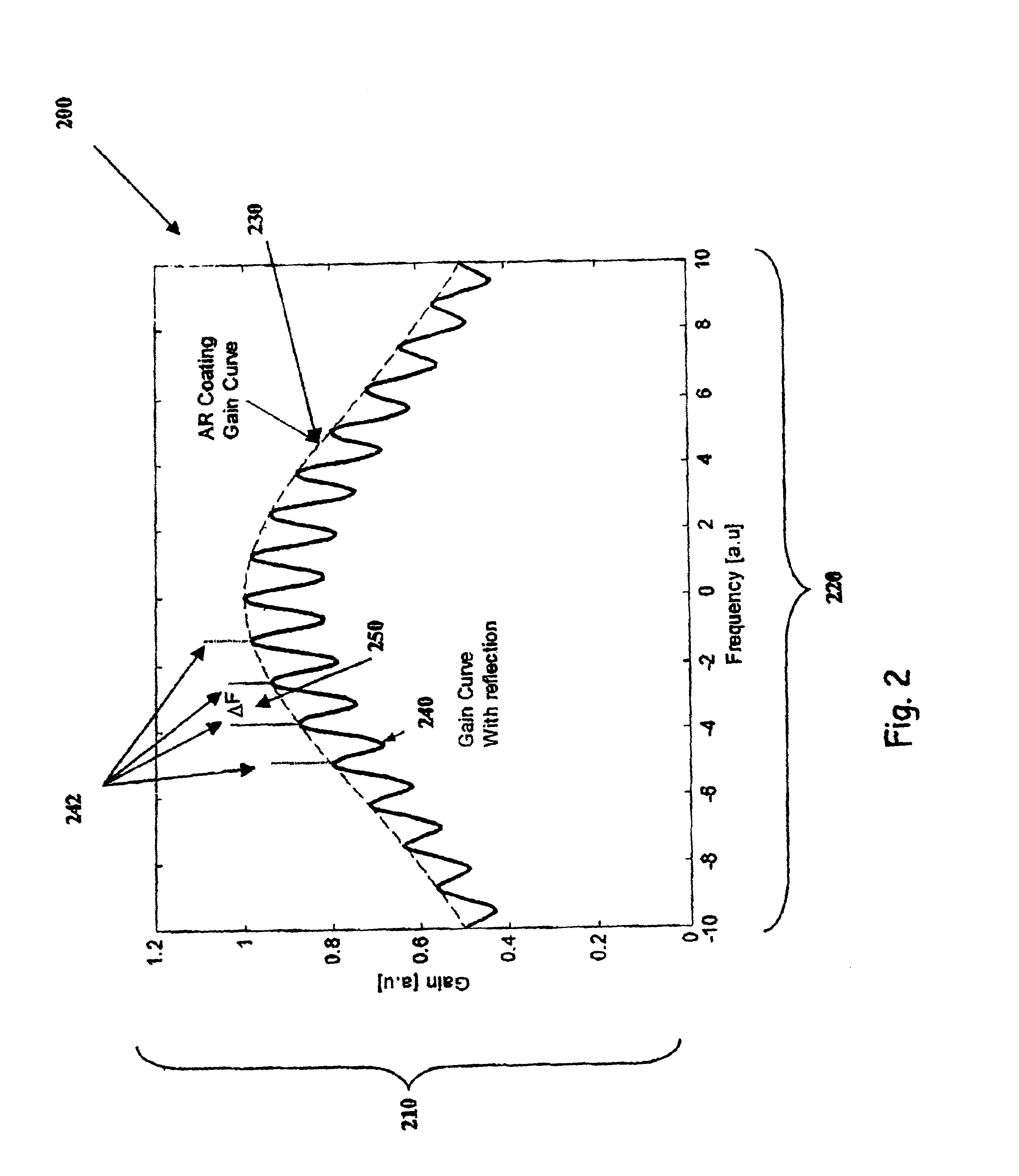
[0013]In the preferred embodiment, a partial reflection coating (PRC) or an imperfect anti-reflection coating (ARC) is used in one facet of the semiconductor amplifier as compared to an almost perfect anti-reflection coating. This side of the laser amplifier is extended to a chirped, fiber-grating reflector. The other facet has a regular broadband high reflection (HR) coating. The length of the semiconductor amplifier is selected such that the spacing ΔF between its longitudinal modes matches the standard ITU spacing, which is 100 GHz, or any other nonstandard or sub-spacing, such as 50 GHz or even 25 GHz. More specifically, the length is taken to be: Lsc=(c / nsc) / (2ΔF), where Lsc and nsc are the semiconductor length and its index of refraction, respectively. The partially reflecting layer together with the HR coating layer, forming the Fabry-Perot etalon laser diode of length Lsc, function as a periodic filter that effectively modulates the gain curve of the semiconductor amplifier with the required frequency spacing ΔF. This shape of gain curve represents the introduction of a wavelength stabilization mechanism for the extended cavity. It is most likely, that when a wavelength is selected by modulating the gain medium with the RF frequency that matches the extended cavity defined by a small section of the grating with the selected Bragg wavelength (or optical frequency), the peak in the gain curve that is the closest to the selected wavelength will be excited. By controlling the temperature and DC bias current of the semiconductor amplifier, these peaks in the effective gain curve can be placed accurately at their required location, and in that way the plurality of possible emitted wavelengths are fixed accordingly.

Problems solved by technology

Most of today's communication systems are known as passive systems, meaning that the particular wavelengths are assigned to particular addresses and there is a limited ability to change these dynamically during the communication.
Dynamically tunable light sources that might be used for routing of optical information packets exist, however, today they are not well developed.
This causes large discrepancies between the roundtrip time of the shortest cavity formed with the reflector that is the closest to the laser facet, and the longest one formed with the last Bragg reflector.
This therefore complicates the cavity design from the degeneracy of harmonics mode-locking point of views and increases the differences between the bit-rates of the different emitted wavelengths.
This fact raises wavelength stability problems for the extended cavity with the chirped grating; all the wavelengths that are found in the strip of width ΔL in the chirped grating are allowed.

Method used


Image

  • Tunable laser with a fixed and stable wavelength grid especially useful for WDM in fiber optic communication systems
  • Tunable laser with a fixed and stable wavelength grid especially useful for WDM in fiber optic communication systems
  • Tunable laser with a fixed and stable wavelength grid especially useful for WDM in fiber optic communication systems

Examples


Embodiment Construction

[0019]Referring now to FIG. 1, there is shown a schematic illustration of an exemplary embodiment a system 100 for wavelength tunable optical transmitter, constructed and operated according to the principles of the present invention.

[0020]System 100 shows a laser cavity 105 having a laser diode 110, for use as the gain element, with a chirped grating 120. Laser diode 110 has at one end a broad band high reflective coating (HRC) 113, and at the other end a partial reflective coating (PRC) 116 to allow interaction with chirped grating 120, thus extending the laser diode cavity 110 to chirped grating 120. The laser is an active modulation element using a biased sinusoidal current source 102 with a frequency fRF, that provides the mode-locking for the specific cavity length formed by HRC 113 mirror, and a portion of the chirped grating located at integer multiples of L=(c / n) / (2nfRF) from HRC 113. The central reflectivity of this portion determines the laser-emitted wavelength.

[0021]Alte...


PUM


Abstract

A wavelength tunable mode-locked laser system including a complex laser cavity comprising a broadband reflective mirror at one end and a wavelength chirped selective mirror at the other end. The system further includes a gain element and a low finesse Fabry-Perot etalon element inside the laser cavity. The gain element may be a semiconductor laser chip, with a broadband high reflection coating at one end and a partially reflecting coating at its other end. The gain element has a well-defined length, such that its longitudinal modes match a required optical frequency grid. The system also includes an active modulation element applied externally on said complex laser cavity to provide mode-locking of a specific cavity length among said defined predetermined cavity lengths, such that all possible optical frequencies emitted by the laser system are stabilized to the linear grid dictated by the Fabry-Perot longitudinal modes, that could be in accordance with the International Telecommunications Union Standards.

Description

[0001]Claim(s) to Priority; U.S. Provisional patent application, filed Jul. 1, 2002, Ser. No. 60 / 392,301.FIELD OF THE INVENTION[0002]The present invention relates to fiber optic communication systems and devices, and other optical systems. More particularly the present invention relates to a system, which enables the introduction of many wavelengths in WDM (Wavelength Division Multiplexing) fiber optic communication systems, by use of a tunable source.BACKGROUND OF THE INVENTION[0003]Fiber-optic communications is a most important method of communications. A large amount of information is transferred via fiber optics systems. Examples of such communications beyond telephones are Internet and cable TV networks. The present commercial transmission rate of a single fiber with a single wavelength can reach as high as 10 Gb / second. A way to expand the transmission capacity is by the use of more than one wavelength on a single optical fiber. This technology is called WDM.[0004]The state of...

Claims


Application Information

Patent Timeline
Patent Type & Authority Patents(United States)
IPC IPC(8): H01S3/10H01S5/028H01S5/062H01S5/14
CPCH01S5/028H01S5/146H01S5/06213H01S5/141
Inventor FISCHER, BARUCH
Owner MRV COMM LTD 50
Learn More