Spectroscopically measured overlay target

a target and spectroscopic technology, applied in the field of overlay target, can solve the problems of reducing overlay alignment tolerances, difficult to measure the alignment accuracy of one masking level to the previous level, and increasing the difficulty of one masking level to measure the alignment accuracy to the previous level

Inactive Publication Date: 2006-06-13
ONTO INNOVATION INC
View PDF98 Cites 227 Cited by
  • Summary
  • Abstract
  • Description
  • Claims
  • Application Information

AI Technical Summary

Benefits of technology

[0013]In another aspect of the present invention, an apparatus for spectroscopically measuring the lateral alignment of layers on a substrate by way of an overlay target composed of overlaying diffraction gratings includes a light source for producing broadband light to be incident on the overlay target and a light detector for spectroscopically detecting light that is diffracted from the overlay target. In addition, the apparatus includes a computer and a computer-usable medium having computer-readable program code embodied therein for causing the computer to determine a lateral overlay error based on the light that is diffracted from the overlay target. The code embodied in the computer-usable medium can cause the computer to perform the steps of constructing an optical model of the overlay target,

Problems solved by technology

However, as the integrated circuit feature sizes continue to decrease to provide increasing circuit density, it becomes increasingly difficult to measure the alignment accuracy of one masking level to the previous level.
This overlay metrology problem becomes particularly difficult at submicrometer feature sizes where overlay alignment tolerances are reduced to provide reliable semiconductor devices.
Conventional imaging devices, unfortunately, suffer from disadvantages such as sensitivity to vibration and cost.
Moreover, conventional imaging devices su

Method used


Image

  • Spectroscopically measured overlay target
  • Spectroscopically measured overlay target
  • Spectroscopically measured overlay target

Examples


Embodiment Construction

[0031]In accordance with an embodiment of the present invention, an overlay target is spectroscopically measured, which advantageously avoids problems associated with high magnification. In one embodiment, the overlay target is asymmetrical, which advantageously increases sensitivity in the spectroscopic measurement. Additionally, the overlay target can be optimized for sensitivity.

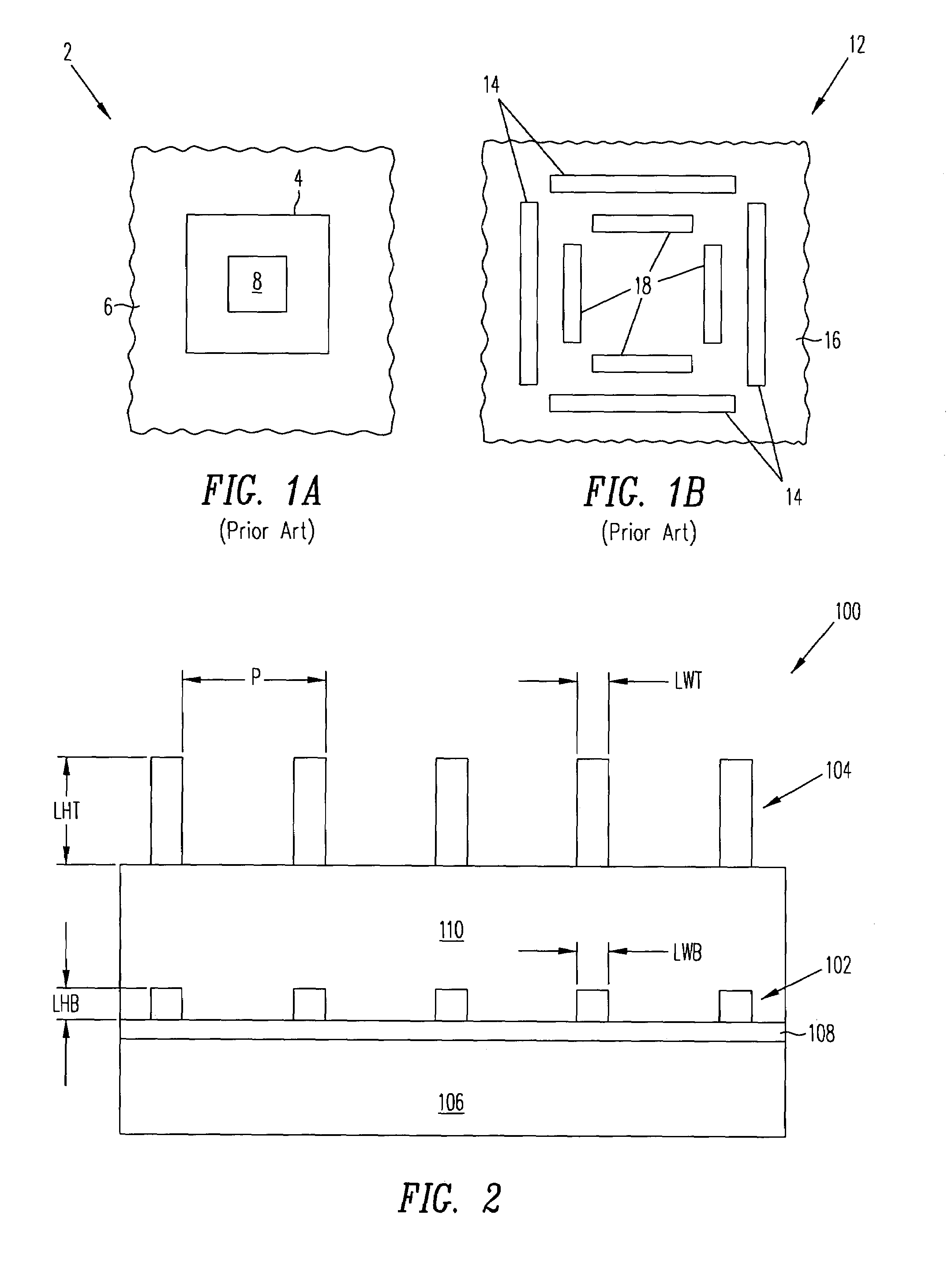
[0032]FIG. 2 shows a cross sectional view of an overlay target 100 in accordance with an embodiment of the present invention. Overlay target 100 includes two sets of diffraction grating structures; a bottom diffraction grating 102 and a top diffraction grating 104. Overlay target 100 is produced on a substrate 106, which is e.g., a silicon substrate, and any overlying layers, shown as layer 108, which may be a gate oxide layer, which is e.g., 3.5 nm thick. The bottom diffraction grating 102 is produced, for example, by producing a layer of appropriate material, such as a 200 nm layer of polysilicon, follo...


PUM


Abstract

An overlay target for spectroscopic measurement includes at least two diffraction gratings, one grating overlying the other. The diffraction gratings may include an asymmetry relative to each other in order to improve resolution of the presence as well as the direction of any mis-registration. For example, the asymmetry between the two diffraction gratings may be a phase offset, a difference in pitch, line width, etc. The overlay target may be spectroscopically measuring, for example, using an optical model and a best fit analysis. Moreover, the overlay target may be optimized by modeling the overlay target and adjusting the variable parameters and calculating the sensitivity of the overlay target to changes in variable parameters.

Description

BACKGROUND OF THE INVENTION[0001]1. Field of the Invention[0002]The present invention relates to overlay metrology, and in particular to an overlay target that can be accurately measured spectroscopically.[0003]2. Discussion of the Related Art[0004]Semiconductor processing for forming integrated circuits requires a series of processing steps. These processing steps include the deposition and patterning of material layers such as insulating layers, polysilicon layers, and metal layers. The material layers are typically patterned using a photoresist layer that is patterned over the material layer using a photomask or reticle. Typically the photomask has alignment targets or keys that are aligned to fiduciary marks formed in the previous layer on the substrate. However, as the integrated circuit feature sizes continue to decrease to provide increasing circuit density, it becomes increasingly difficult to measure the alignment accuracy of one masking level to the previous level. This ov...

Claims


Application Information

Patent Timeline
IPC IPC(8): G01B11/00
CPCG02B27/4255G03F7/70683G03F7/70633G02B27/4272G01N21/956
Inventor LOWE-WEBB, ROGER R.
Owner ONTO INNOVATION INC
Why Eureka
Try Eureka