Method for indirect-electrification-type continuous electrolytic etching of metal strip and apparatus for indirect-electrification-type continuous electrolytic etching

Active Publication Date: 2006-06-20
NIPPON STEEL CORP
View PDF12 Cites 12 Cited by
  • Summary
  • Abstract
  • Description
  • Claims
  • Application Information

AI Technical Summary

Benefits of technology

[0028](10) A method for indirect-electrification-type continuous electrolytic etching of a metal strip according to any one of the items (1) to (3), characterized by controlling the value of pH of the electrolyte to 2 or higher and 11 or lower.
[0029](11) A method for indirect-electrification-type continuous electrolytic etching of a metal strip according to any o

Problems solved by technology

However, if a common method using laser beam irradiation is employed for the magnetic domain refinement, its effect is lost during the stress-relief annealing, at about 800° C., applied after the steel sheet is assembled into the form of a wound transformer core at a user's plant.
With regard to the method of forming grooves by electrolytic etching prior to final annealing, on the other hand, while it is superior to the spraying method in the control of groove depth, if there are portions where the recrystallization during the final annealing is poor and said effect is not obtained after the groove formation but, rather, an adverse effect to deteriorate the property results.
None of these production methods satisfies both the selectivity to allow the groove formation only at the portions of good recrystallization and the controllability of the groove depth, and none can be viewed as really excellent industrially.
However, it is difficult, by the indirect electrification method, to precisely control the amount of etching owing to a short circuit current, as seen in the problem recognized in the invention of an apparatus for direct-electrification-type electrolytic etching disclosed in Japanese unexamined Patent Publication No.
By such a conventional technology, the surface of a metal strip that can be electrolytically etched in one process using an electrically insulating etching resist formed into etching patterns is inevitably lim

Method used


Image

  • Method for indirect-electrification-type continuous electrolytic etching of metal strip and apparatus for indirect-electrification-type continuous electrolytic etching
  • Method for indirect-electrification-type continuous electrolytic etching of metal strip and apparatus for indirect-electrification-type continuous electrolytic etching
  • Method for indirect-electrification-type continuous electrolytic etching of metal strip and apparatus for indirect-electrification-type continuous electrolytic etching

Examples


example

[0085]The present invention is explained concretely based on examples hereafter.

examples 1 to 5

[0086]The metal strips in these examples before electrolytic etching were grain-oriented silicon steel sheets cold-rolled to the final thickness, decarburization-annealed, painted with an anti-sticking agent for annealing consisting of MgO on both the surfaces and dried, then final-annealed, and having tension coating films (insulating coating films of a phosphate) formed through painting and baking on the coating films of forsterite (Mg2SiO4) that had formed during the final annealing on both the surfaces. They were also grain-oriented silicon steel sheets having, in addition, etching patterns formed on one of the surfaces by selectively removing the forsterite coating film and tension coating film using a laser beam to expose the steel base material. Note that, as the tension coating film was an electrically insulating coating film, it was used as the etching mask.

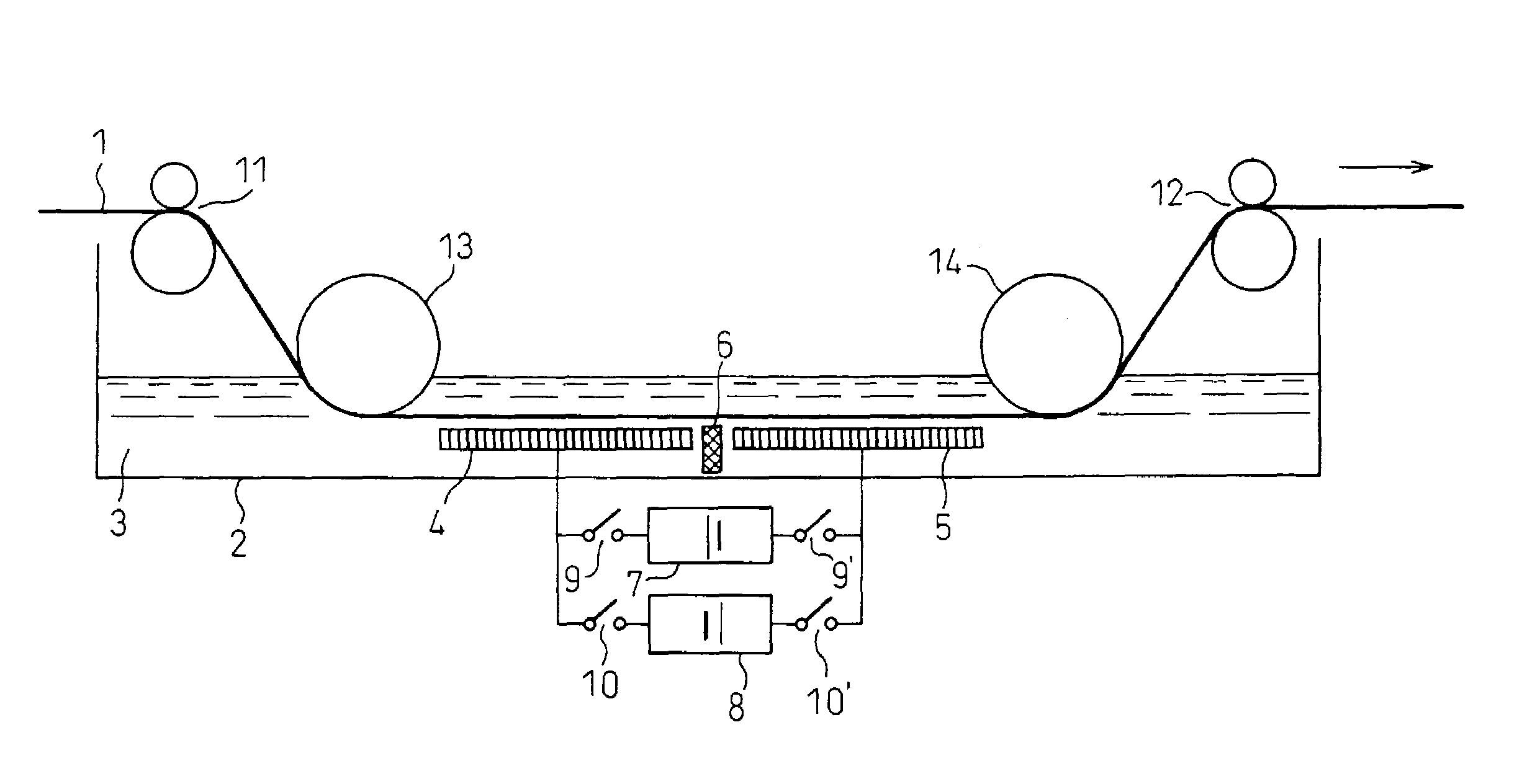
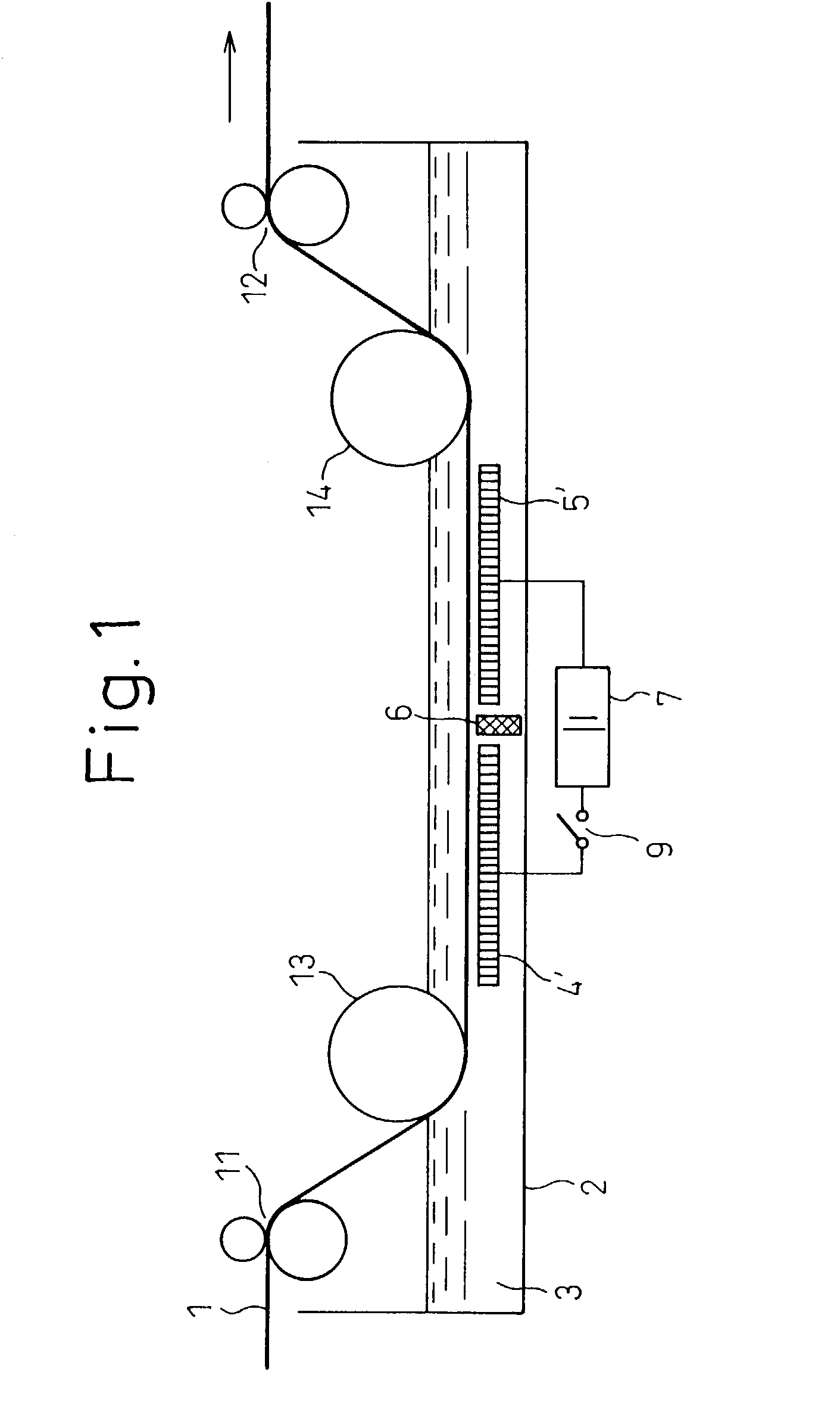
[0087]The grain-oriented silicon steel sheets pretreated as described above were subjected to an electrolytic etching ...

example 6

[0105]Etching patterns, each 0.3 mm in width, were formed at intervals of 6 mm by laser beam irradiation on steel sheets which had been finish-rolled to a thickness of 0.23 mm by cold rolling, final-annealed as grain-oriented electrical steel sheets and painted with insulating coating films, and, then, the steel sheets were processed in an electrolysis tank in which a cathode and an anode were arranged alternately so as to face the surface of the steel sheets where the steel base material was partially exposed. Here, a 5%-aqueous solution of sodium chloride was used as the electrolyte and its pH value was adjusted using sodium hydroxide and hydrochloric acid. The etching was conducted under different values of pH ranging from 1 to 12.

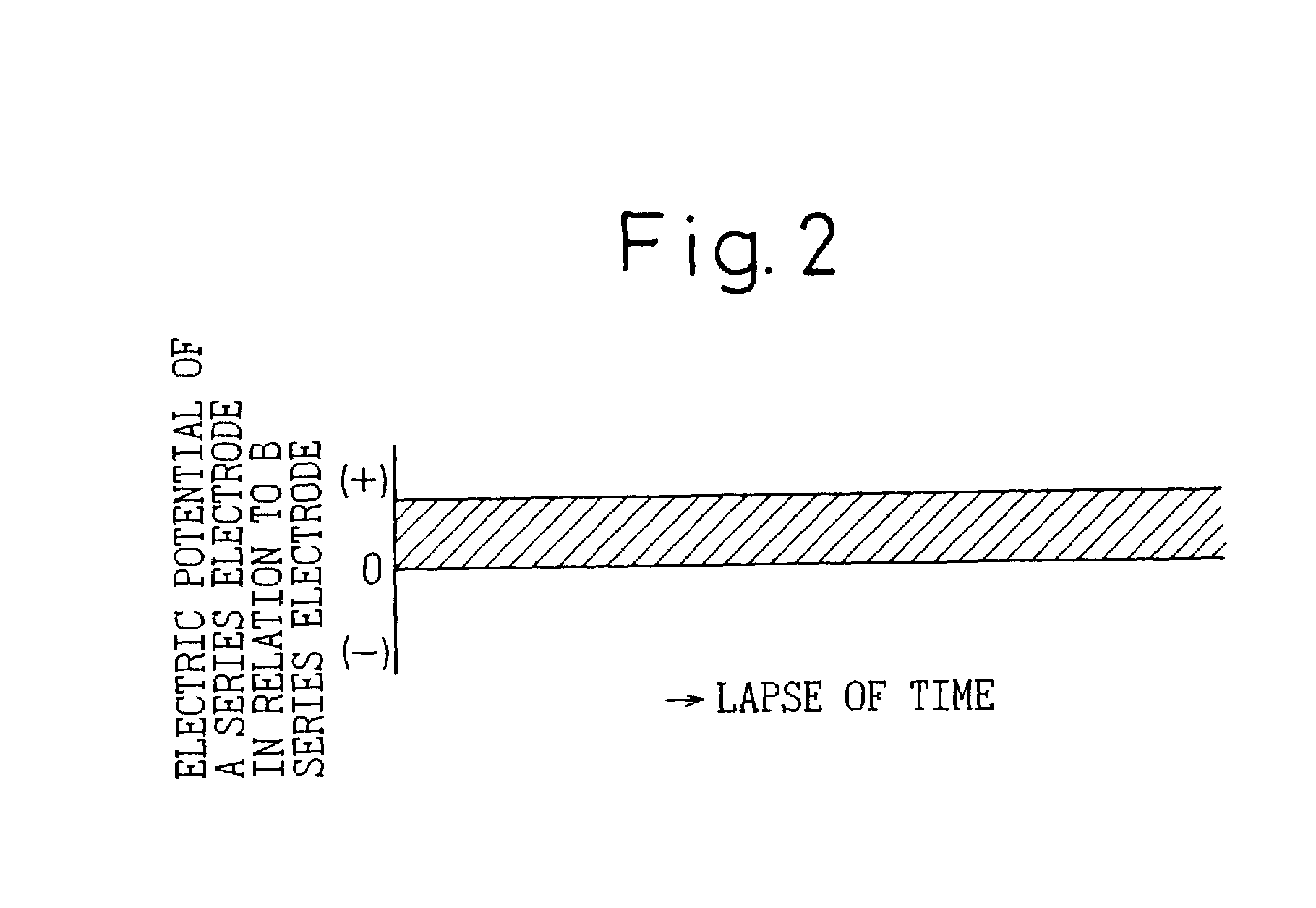
[0106]The specimens according to the present invention were taken out and the shapes of grooves were examined; grooves about 20 μm in average depth had been formed. Table 2 shows the result of the investigation of the amounts of iron precipitation in th...


PUM

PropertyMeasurementUnit
Currentaaaaaaaaaa
Digital informationaaaaaaaaaa
Timeaaaaaaaaaa

Abstract

The present invention provides a method for indirect-electrification-type continuous electrolytic etching of a metal strip suitable for producing a low-core-loss, grain-oriented silicon steel sheet not susceptible to the deterioration of core loss after stress-relief annealing, and an apparatus for the indirect-electrification-type continuous electrolytic etching. It is a method for indirect-electrification-type continuous electrolytic etching of a metal strip and an apparatus for the same for continuously forming grooves by indirect-electrification-type electrolytic etching on a metal strip on which an etching mask is formed in etching patterns on one or both surfaces, wherein: plural electrodes of an A series and a B series are arranged alternatively, at least in a pair, in said order in the travelling direction of the metal strip so that they face the surface to be etched of the metal strip on which the etching patterns are formed; the space between the metal strip and the group of the electrodes is filled with an electrolyte; and voltage is applied across the A series and B series electrodes.

Description

CROSS-REFERENCE TO RELATED APPLICATIONS[0001]This application claims priority under 35 U.S.C. 119 from Japanese Patent Application No. 2002-056749 filed on Mar. 4, 2002, and from Japanese Patent Application No. 2002-236913 filed on Aug. 15, 2002. The entire disclosures of these applications are incorporated herein by reference.[0002]1. Technical Field[0003]The present invention relates to a method for indirect-electrification-type continuous electrolytic etching of a metal strip and an apparatus for the indirect-electrification-type continuous electrolytic etching, and, in particular, to a method for indirect-electrification-type continuous electrolytic etching of a metal strip suitable for producing a low-core-loss, grain-oriented silicon steel sheet, not susceptible to the deterioration of core loss after stress-relief annealing, used for the magnet core of a power supply transformer and the like, and an apparatus for the indirect-electrification-type continuous electrolytic etchi...

Claims


Application Information

Patent Timeline
IPC IPC(8): C25F3/06C25F3/14C25F7/00
CPCC25F3/06C25F7/00C25F3/14
Inventor MOGI, HISASHINOMURA, NARUHIKOKOGA, SHIGENOBUFUJIKURA, MASAHIROYAMAZAKI, SHUICHI
Owner NIPPON STEEL CORP
Why Eureka
Try Eureka