
Multi-color image forming material and multi-color image forming method

a technology of multi-color image and forming material, applied in the direction of diffusion transfer process, thermography, instruments, etc., can solve the problems of insufficient resolution, blurred halftone dots, and insufficient recording halftone dots, etc., to achieve excellent print conformity, high stability, and high grade

Inactive Publication Date: 2006-08-01
FUJIFILM CORP +1
View PDF21 Cites 12 Cited by
  • Summary
  • Abstract
  • Description
  • Claims
  • Application Information

AI Technical Summary

Benefits of technology

The invention provides a multicolor image forming material and method that solves problems of prior art such as poor print quality and stability of halftone dots, and delicate texture drawing or reduction of accurate paper white. The material has excellent register accuracy and transfer properties onto wood-free paper, and can undergo large-size printing without losing quality. The material also has good accumulation and resolution, and does not generate wrinkles or scuffing during cutting. The invention provides a solution for improving the quality of multicolor image recording.

Problems solved by technology

However, all of these systems involved such a problem that the recording halftone dot shape is not sharp.
The laser sublimation system (1) involved such problems that since it uses a dye as the coloring material, approximation property to a printed matter is not sufficient and that since it is a system in which the coloring material is sublimated, outlines of halftone dots get blurred so that the resolution is not sufficiently high.
However, since this system is a system in which the coloring material scatters, it involved such a problem that likewise the sublimation system, outlines of halftone dots get blurred so that the resolution is not sufficiently high.
Further, the laser fusion system (3) involved such a problem that since fused materials flow, clear outlines do not appear.
If recording is performed with laser beam made of multiple beams using a conventional thermal transfer sheet, there may be the case where the image density of a transferred image formed on an image receiving sheet is insufficient.
Further, there were encountered such problems that the register accuracy is not sufficient and that wrinkles are liable to be generated at the time of actual paper stock transfer.
Also, there was the case of causing such an inconvenience that in accumulating image receiving sheets having an transferred image onto a printed thermal transfer sheet as laminated after image transfer from a variety of thermal transfer sheets to image receiving sheets in a tray, etc., the thermal transfer sheets are dropped from the tray, or the image receiving sheets are curled.
Also, there was encountered such a problem that when the size is made large, traveling property of thermal transfer sheets or image receiving sheets becomes difficult, or jamming or other troubles are generated.
Moreover, there was encountered such a problem that the image quality is reduced by scuffing of the cut surface because of cutting failure of thermal transfer sheets, or foreign matters such as contaminants generated during cutting.

Method used


Image

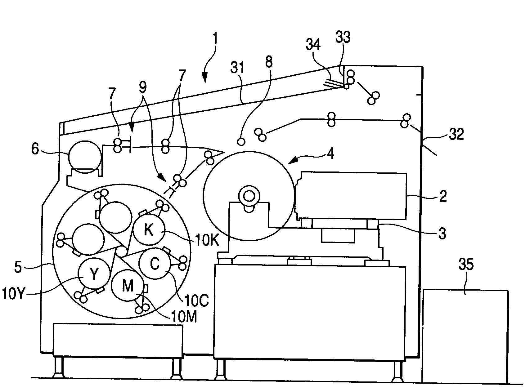
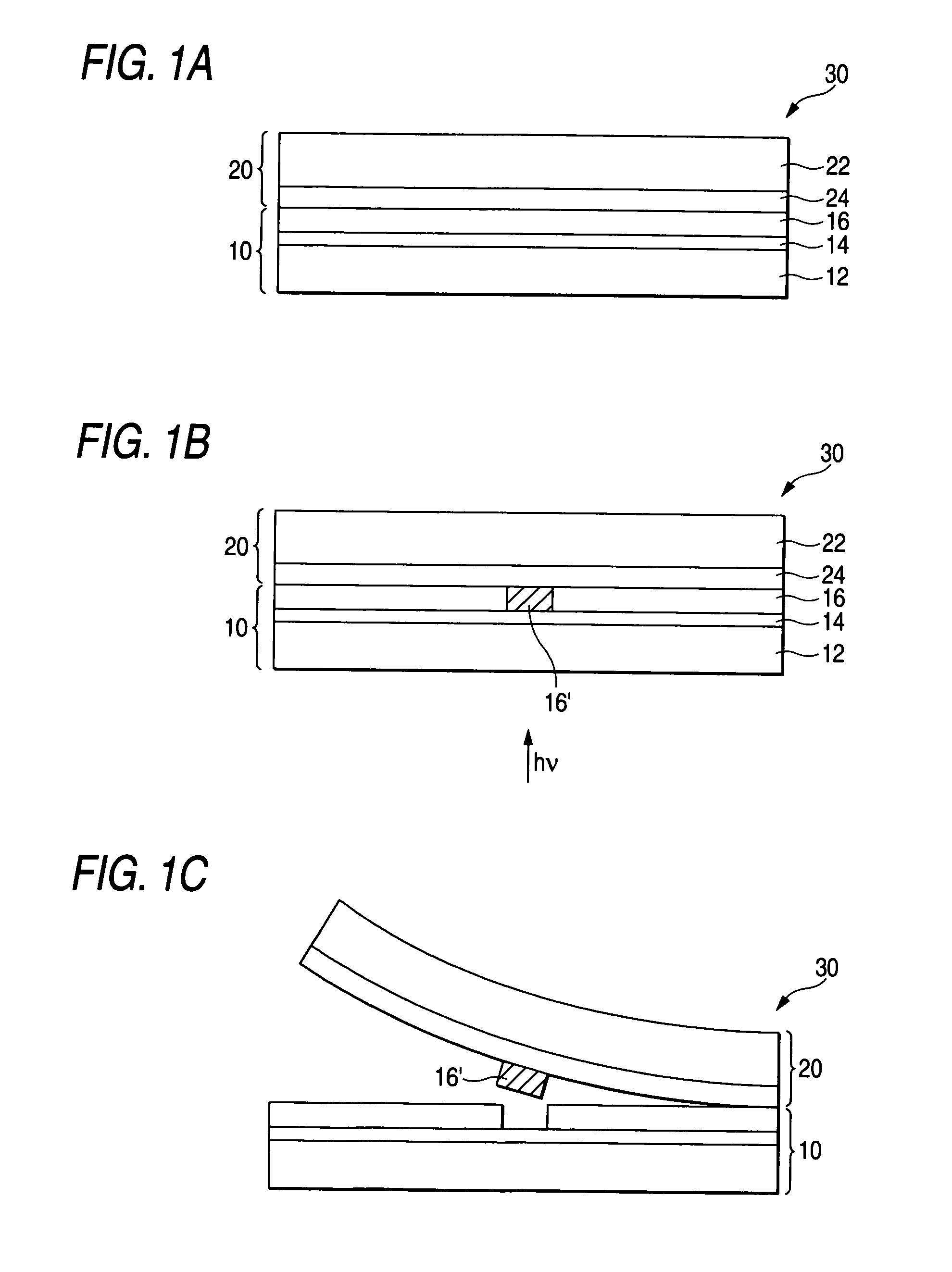
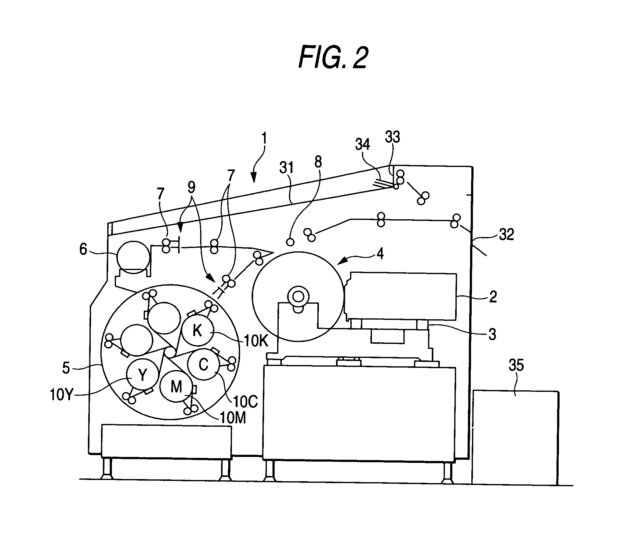
  • Multi-color image forming material and multi-color image forming method
  • Multi-color image forming material and multi-color image forming method
  • Multi-color image forming material and multi-color image forming method

Examples


example 1-1

Preparation of Thermal Transfer Sheet K (Black)

[Formation of Back Layer]

[0381]

[Preparation of coating solution for first back layer]Aqueous dispersion of acrylic resin (Jurymer2partsET410, manufactured by Nihon Junyaku Co., Ltd.,solids content: 20% by weight):Antistatic agent (aqueous dispersion of tin7.0partsoxide-antimony oxide) (mean particle size: 0.1μm, 17% by weight):Polyoxyethylene phenyl ether:0.1partsMelamine compound (Sumitics Resin M-3,0.3partsmanufactured by Sumitomo Chemical Co., Ltd.):Distilled water:To make 100parts in total

[Formation of First Back Layer]

[0382]One surface (back surface) of a biaxially stretched polyethylene terephthalate support having a thickness of 75 μm (the both surfaces of which had an Ra of 0.01 μm) was subjected to corona treatment, and the coating solution for first back layer was coated in a dry layer thickness of 0.03 μm, followed by drying at 180° C. for 30 seconds to form a first back layer. The support has a Young's modulus of 450 kg / mm2 ...

example 2-1

Preparation of Thermal Transfer Sheets K, Y, M and C

[0473]Thermal transfer sheets K (black), Y (yellow), M (magenta) and C (cyan) were prepared in the same manner as in Example 1-1, except that in Example 1-1, a matting agent dispersion having the following formulation was used as the matting agent dispersion in preparing a coating solution for photothermal converting layer. The physical properties of the photothermal converting layer and the image forming layer in each of the thermal transfer sheets were substantially identical with those obtained in Example 1-1.

Formulation of Matting Agent Dispersion:

[0474]

N-Methyl-2-pyrrolidone (NMP):69partsMethyl ethyl ketone:20partsStyrene-acrylic resin (Joncryl 611,3partsmanufactured by Johnson Polymer Corporation):SiO2 particle (Seahostar KE-P150, manufactured8partsby Nippon Shokubai Co., Ltd., which is a silicaparticle):

Preparation of Image Receiving Sheet

[0475]A coating solution for cushioning layer having the same formulation as in Example...

example 2-2

[0493]An image receiving sheet was prepared, and a transferred image was formed in the same manner as in Example 2-1, except that in Example 2-1, a biaxially stretched polyethylene terephthalate support having a thickness of 97 μm as used in the thermal transfer sheet was used in place of the white PET (polyethylene terephthalate) support (Lumirror #130E58, manufactured by Toray Industries, Inc., thickness: 130 μm) as used in the image receiving sheet. As a result, an image similar to that in Example 2-1 was obtained.

[0494]The image receiving layer of the resulting image receiving sheet had the following physical properties.

[0495]The surface roughness Ra was 0.3 μm. The surface waviness of the image receiving layer was 1.2 μm. The Smooster's value of the surface of the image receiving layer at 23° C. and 55% RH of was 8 mmHg (≅1.1 kPa). The coefficient of static friction of the surface of the image receiving slayer was 037.


PUM

PropertyMeasurementUnit
sizeaaaaaaaaaa
rate of heat shrinkageaaaaaaaaaa
contact angleaaaaaaaaaa

Abstract

A multicolor image forming material in which a laser beam irradiated region of an image forming layer of a thermal transfer sheet is transferred onto an image receiving layer of an image receiving sheet, wherein: (a) a rate of heat shrinkage in the machine direction and a rate of heat shrinkage in the traverse direction of the image receiving sheet are both not more than 1% with the rate of heat shrinkage in the traverse direction being smaller than the rate of heat shrinkage in the machine direction, (b) a coefficient of dynamic friction between the thermal transfer sheet surface and the image receiving sheet surface is not more than 0.70, (c) a stiffness in the machine direction (Msh) and a stiffness in the traverse direction (Tsh) of the thermal transfer sheet are both from 30 to 70 g, a stiffness in the machine direction (Msr) and in the traverse direction (Tsr) of the image receiving sheet are both from 40 to 90 g, Msh / Tsh and Msr / Tsr are each from 0.75 to 1.20 and (Msr−Msh) and (Tsr−Tsh) are each from 10 g to 40 g or (d) at least the magenta thermal transfer sheet has a breaking stress from 150 to 300 MPa in both machine (MD) and crosswise (CD) directions with the breaking stress in the crosswise direction being at least 10 MPa larger than in the machine direction and a breaking elongation of from 80 to 300% in both machine and crosswise directions with the breaking elongation in the machine direction being at least 5 % larger than in the crosswise direction.

Description

TECHNICAL FIELD[0001]The present invention relates to a multicolor image forming material for forming a full-color image with high resolution using laser beam and a multicolor image forming method using the subject material. In particular, the invention relates to a multicolor image forming material and a color image forming method useful for preparing a color proof in the printing field by laser recording from digital image signals (DDCP: direct digital color proof) or a mask image.BACKGROUND ART[0002]In the graphic art field, printing on a printing plate is carried out using one set of color separating film prepared using a lith film from a color original. In general, prior to regular printing (actual printing works), for the sake of checking errors in the color separation step or necessity of color correction, etc., a color proof is prepared from the color separating film. The color proof is desired to realize a high resolving power enabling high reproducibility of intermediate t...

Claims


Application Information

Patent Timeline
Patent Type & Authority Patents(United States)
IPC IPC(8): G03F7/34G03F7/09G03F7/11B41M5/34B41M5/382B41M5/41B41M5/42B41M5/52G03F3/10
CPCB41M5/345B41M5/38207B41M5/42B41M5/52B41M5/41Y10S430/14
Inventor SHIMOMURA, AKIHIROYOSHINARI, SHINICHIMIYAKE, KAZUHITO
Owner FUJIFILM CORP
Learn More