Optically transparent nanocomposite materials

a nano-composite material, optically transparent technology, applied in the direction of solid-state devices, discharge tube/lamp details, inorganic chemistry, etc., can solve the problem of optical attenuation of composite materials, and achieve the effect of reducing the number of optical attenuation peaks, facilitating formation, and facilitating fiberizability

Inactive Publication Date: 2006-08-22
RUTGERS THE STATE UNIV
View PDF25 Cites 23 Cited by
  • Summary
  • Abstract
  • Description
  • Claims
  • Application Information

AI Technical Summary

Benefits of technology

[0018]Matrix polymers suitable for use with the present invention include thermosetting and thermoplastic organic polymers free of intrinsic optical absorptions that would be a detriment to absorption, fluorescence or luminescence by the active ion. For example, for infrared wavelengths, non-infrared absorbing polymers may be used. Each nanoparticle dispersed in the polymer matrix may be doped with a different active species. The composites of the present invention are easily formed and readily fiberizable.
[0019]The composite materials of the present invention contain highly doped nanoparticles that exhibit broader absorption and luminescence than observed from corresponding prior art materials doped in lower concentrations, in part because of the optical transparency, is transmitted at a level of efficiency heretofore unseen, thereby increasing the transfer and reception of infrared signals. Furthermore, the optical transparency of the nanoparticles permit particle loading levels that further enhance this effect. Optically transparent composite materials with particle loading levels as high as 60 vol. % can be attained. Typically, particle loading will be between about 1 and about 30 vol. %.
[0020]This broadened emission band is advantageous for many luminescent devices, which also take advantage of the versatility of a reduced phonon energy environment. The emission band can be broadened further by combining a plurality of different nanoparticles whose emissions are close to one another by virtue of the choice of host material or active ion dopants and upon excitation, fluorescence or luminescence emit a plurality of overlapping emission bands. The emission band can also be separated into distinct spectral lines by combining a plurality of different nanoparticles, which, through the choice of host material or active ion dopants, emit a plurality of separate and distinct emission bands upon excitation, fluorescence or luminescence.
[0021]Therefore, according to still another aspect of the present invention, a luminescent device is provided incorporating the composite of the present invention. Examples of luminescent devices include zero-loss links, wavelength-division-multiplexing devices, upconversion light sources, standard light sources, and the like. Volumetric displays based on the composites of the present invention exhibit greatly enhanced performance, easier fabrication and reduced weight.
[0022]Composites of nanoparticles doped with different active species exhibit ultra-broad band emissions attributable to the additive effects of the individual dopants, all of which are transmitted with high efficiency. This broadened emissions band is advantageous for the fabrication of sources operating in wavelength-division-multiplexing schemes.

Problems solved by technology

This index difference leads to scattering of light, which is the major cause of optical attenuation for composite materials.

Method used


Image

  • Optically transparent nanocomposite materials
  • Optically transparent nanocomposite materials
  • Optically transparent nanocomposite materials

Examples


example 1

Preparation of SAE / 6F Nanocomposites

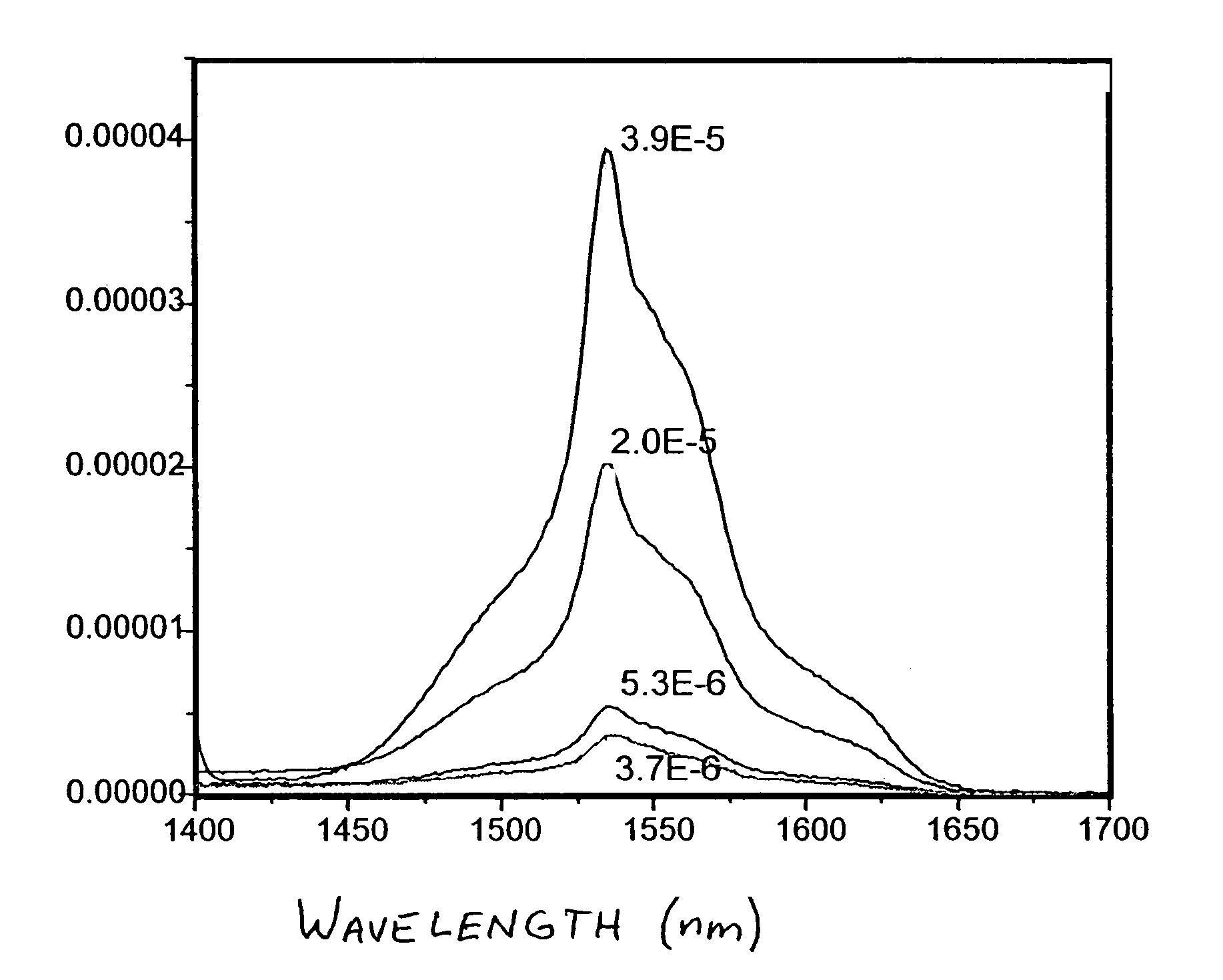
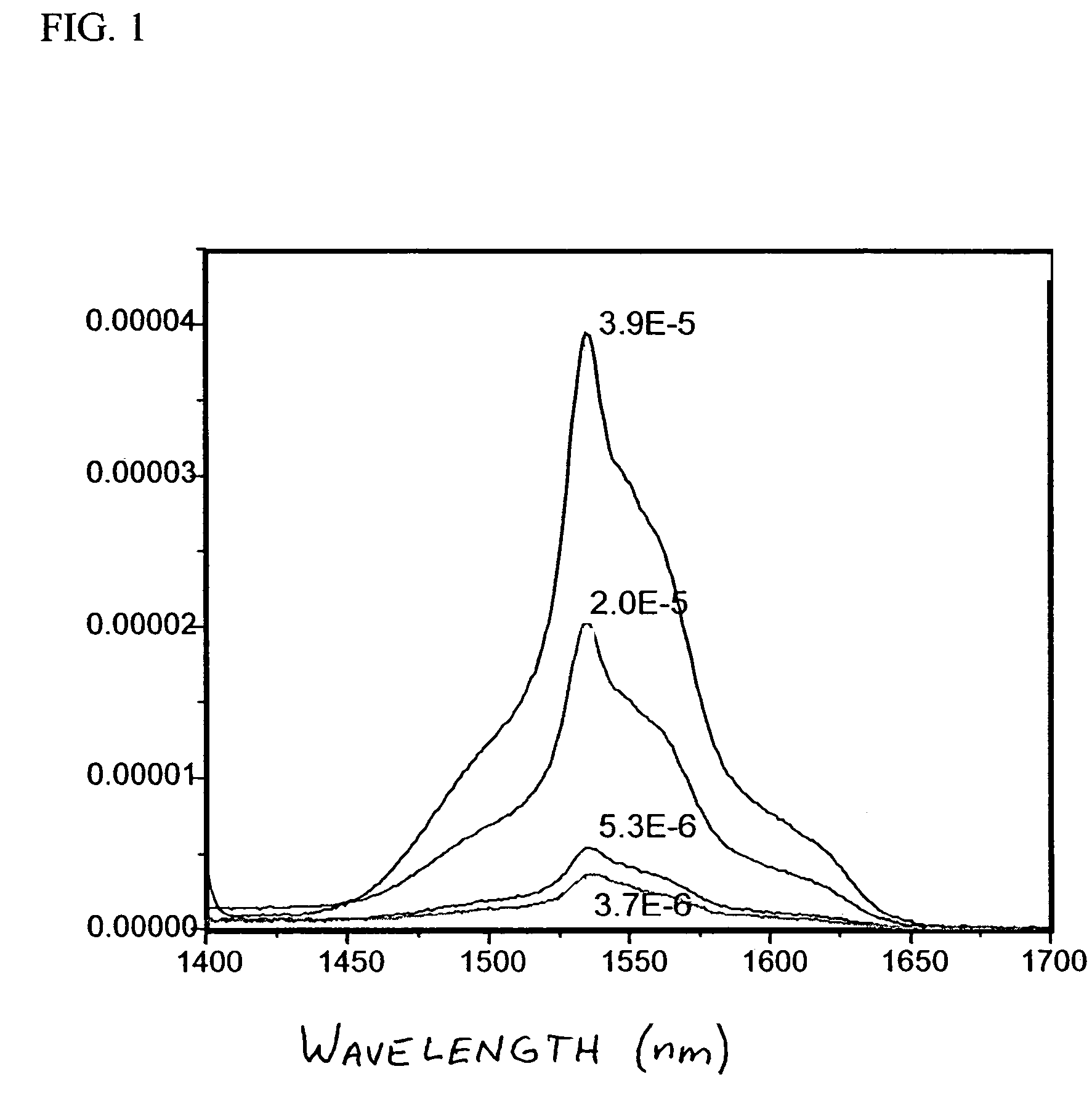
[0051]10 wt % of 6F polymer solutions were used to prepare all the ceramic / polymer nano-composites. The SAE solid loadings in 6F polymer were 3, 5, 10, and 20 wt %. For example, 0.192 g of 6F polymer was dissolved in 1 ml toluene. 10 wt % (0.021 g) SAE was mixed with 1 ml toluene and ultrasonicated for 15 minutes (Ultrasonicator, Model FS30, Fisher Scientific, Fair Lawn, N.J.). The SAE / toluene suspension was mixed with 6F polymer solution by ultrasonicating for an additional 15 minutes. The SAE / 6F composite with 10 wt % SAE loading was cast on a glass slide and oven dried at 50° C. (Isotemp® Oven, model 230Gm Fisher Scientific, Pittsburgh, Pa.). The was repeated for each level of SAE loading. IR emission spectra are shown in FIG. 1, with 3.9 E-5 corresponding to 20 wt % SAE, 2.0 E-5 corresponding to 10 wt % SAE, 5.3 E-6 corresponding to 5 wt % SAE and 3.7 E-6 corresponding to 3 wt % SAE.

example 2

Preparation of Ho-doped LaF3 / 6F Nanocomposites

[0052]Ho—LaF3 / 6F composites were prepared as in Example 1. For example, 0.192 g 6F polymer was dissolved in 1 ml toluene. 10 wt % (0.021 g) Ho—LaF3 was mixed with 1 ml toluene and ultra-sonicated for 15 minutes. The Ho—LaF3 / toluene suspension was mixed with the 6F polymer solution by ultrasonicating for an additional 15 min. The Ho—LaF3 / 6F composite was cast on a glass slide and oven dried at 50° C.

example 3

Preparation of Er—Yb-doped CaF2 Nanocomposites

[0053]Er—Yb-CaF2 (Er, 8 mol %; Yb, 4 mol %) was prepared by the solvothermal method in a solvent mixture of ethylene glycol / water (6.5 / 1, v / v). At room temperature, a solution of Er(OAc)3 (0.64 mmol), Ca(NO3)2 (8 mmol) and Yb(NO3)3 (0.32 mmol) in 22 ml water was added dropwise into an NH4F (18 mmol) ethylene glycol / water solution while stirring. The reaction mixture was stirred at refluxing temperature for 2 hours and cooled to room temperature. The precipitate was separated by centrifugation (15 minutes at 18,000 rpm) and washed with ethanol / water (v / v, 1:1) two times and DI water two times. The product was lyophilized for 48 hours.

[0054]XRD analyses were carried out by a Kristalloflex D-500 powder diffractometer using Ni filtered Cu Kα radiation. The samples were scanned in the 2θ range of 10–70°, at a step size of 0.05 (° / step). Crystallographic identification of the as-prepared CaF2 powders was accomplished by comparing the experimen...


PUM

PropertyMeasurementUnit
particle sizeaaaaaaaaaa
diameteraaaaaaaaaa
particle sizesaaaaaaaaaa

Abstract

Optically transparent composite materials in which solid solution inorganic nanoparticles are dispersed in a host matrix inert thereto, wherein the nanoparticles are doped with one or more active ions at a level up to about 60 mole % and consist of particles having a dispersed particle size between about 1 and about 100 nm, and the composite material with the nanoparticles dispersed therein is optically transparent to wavelengths at which excitation, fluorescence or luminescence of the active ions occur. Luminescent devices incorporating the composite materials are also disclosed.

Description

CROSS-REFERENCE TO RELATED APPLICATION[0001]The present invention is a Continuation-In-Part of U.S. patent application Ser. No. 09 / 272,912 filed Mar. 19, 1999, now U.S. Pat. No. 6,699,406, the disclosure of which is incorporated by reference.BACKGROUND OF THE INVENTION[0002]The present invention relates to composite materials having dispersed therein optically transparent solid solution inorganic nanoparticles doped with one or more active ions. The present invention also relates to luminescent devices incorporating the composite materials.[0003]Halide salts have received world-wide attention as materials for a myriad of photonic applications. This results from a chemistry in which the ionic species are of generally greater atomic mass and weaker bonding than oxide-based compounds. This intrinsically results in a greatly enhanced theoretical transparency-hence there is substantial interest from telecommunication companies looking for ultra-low loss halide (predominantly fluoride) op...

Claims


Application Information

Patent Timeline
Patent Type & Authority Patents(United States)
IPC IPC(8): C09K11/02H01L51/50C01F17/00C09K11/08C09K11/61C09K11/62C09K11/66C09K11/77C09K11/85C09K11/86C09K11/88G09F13/20H01J61/44H01S3/06H01S3/16H01S5/00H05B33/14
CPCB82Y30/00C01B9/08C01F17/0031C09K11/02C09K11/7701C09K11/7704C09K11/7705C09K11/7706C09K11/7767C09K11/777C09K11/7772C09K11/7773H01S3/0602C01B9/02H01S3/169C01P2002/52C01P2002/54C01P2002/84C01P2004/64H01S3/1608H01S3/1618Y10S977/775Y10S977/776C01F17/36C09K11/77064
Inventor RIMAN, RICHARD E.BALLATO, JOHN
Owner RUTGERS THE STATE UNIV
Why Eureka
Try Eureka