Method and device for manufacturing laminated plate

a technology of laminated plates and manufacturing methods, applied in the directions of packaging, transportation and packaging, labelling, etc., can solve the problems of insufficient heat resistance of conventional epoxy resin and acrylic resin adhesives, inability to heat fusion, and easy appearance of wrinkles on processed laminates

Inactive Publication Date: 2006-09-05
KANEKA CORP
View PDF10 Cites 33 Cited by
  • Summary
  • Abstract
  • Description
  • Claims
  • Application Information

AI Technical Summary

Benefits of technology

[0057]In the device according to the present invention, th...

Problems solved by technology

More particularly, protective materials may be used when the problems such as the appearance of scratches and scars on the surfaces of metallic foils (JP No. 60-109835) and the occurrence of warping of laminates when using a curing oven after thermal laminating (JP No. 4-89254), or the inhibition of smoother lamination caused by poorly evened with resin puddle impregnated paper or impregnated glass cloths, and the like arise.
On the contrary, thermal fusion is impossible unless heating at a temperature higher than the glass transition temperature (Tg) of the thermoplastic resin constituting bonding layers when producing thermally fusible laminates.
There was a problem that visual defects such as wrinkles may easily appear on the processed laminates at such a high temperature because of large change in thermal expansion and thermal shrinkage of the laminating materials.
Recently, however, heat resistance of substrates for on-vehicle systems used in bad environment such as high temperatures and heat resistance to solder reflow in lead-free soldering at a melting point higher than conventional solders by some ten degrees, and the like have been required as substrate characteristics, so that the conventional epoxy resin and acrylic resin adhesives have been regarded as insufficient in heat resistance.
This method was, however, not satisfactory as circuit board materials because wrinkles, waviness, and warp, and the like appear on polyimide metal clad laminates caused by thermal shrinkage at the time of drying and curing the solvents when directly applying, drying, and curing the varnishes.
Due to presence of micro voids with a diameter of 10 to 50 μm between the metallic foil and thermoplastic polyimide layer, the polyimide metal laminate was not good enough as a fine circuit pattern.
For example, JP No. 10-126035 describes “Since an insulating film is lengthened and is laminated on a copper foil (a copper foil is hardly lengthened) in this state by the effects of tension in the adhesion process when the above-mentioned producing method is adopted, there are problems with the shrinking of a flexible printed ...

Method used


Image

  • Method and device for manufacturing laminated plate
  • Method and device for manufacturing laminated plate
  • Method and device for manufacturing laminated plate

Examples


example 1

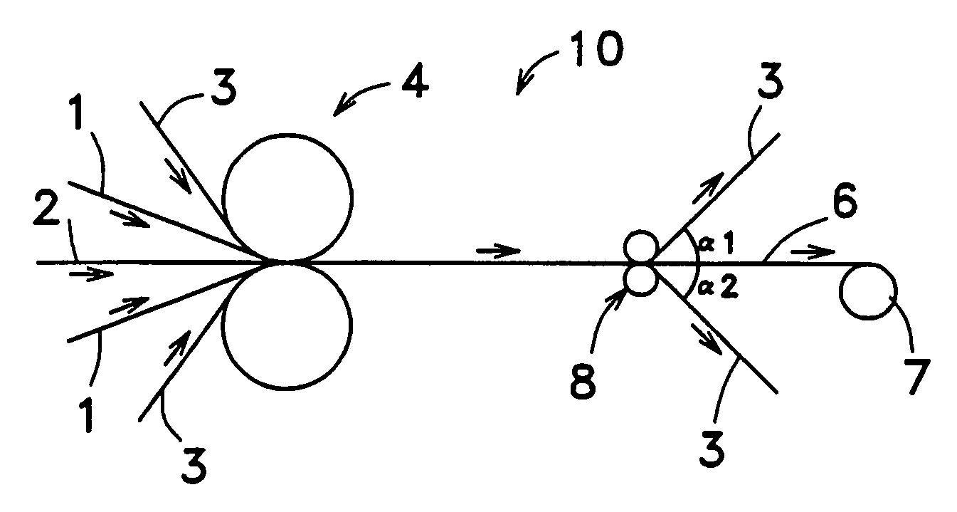
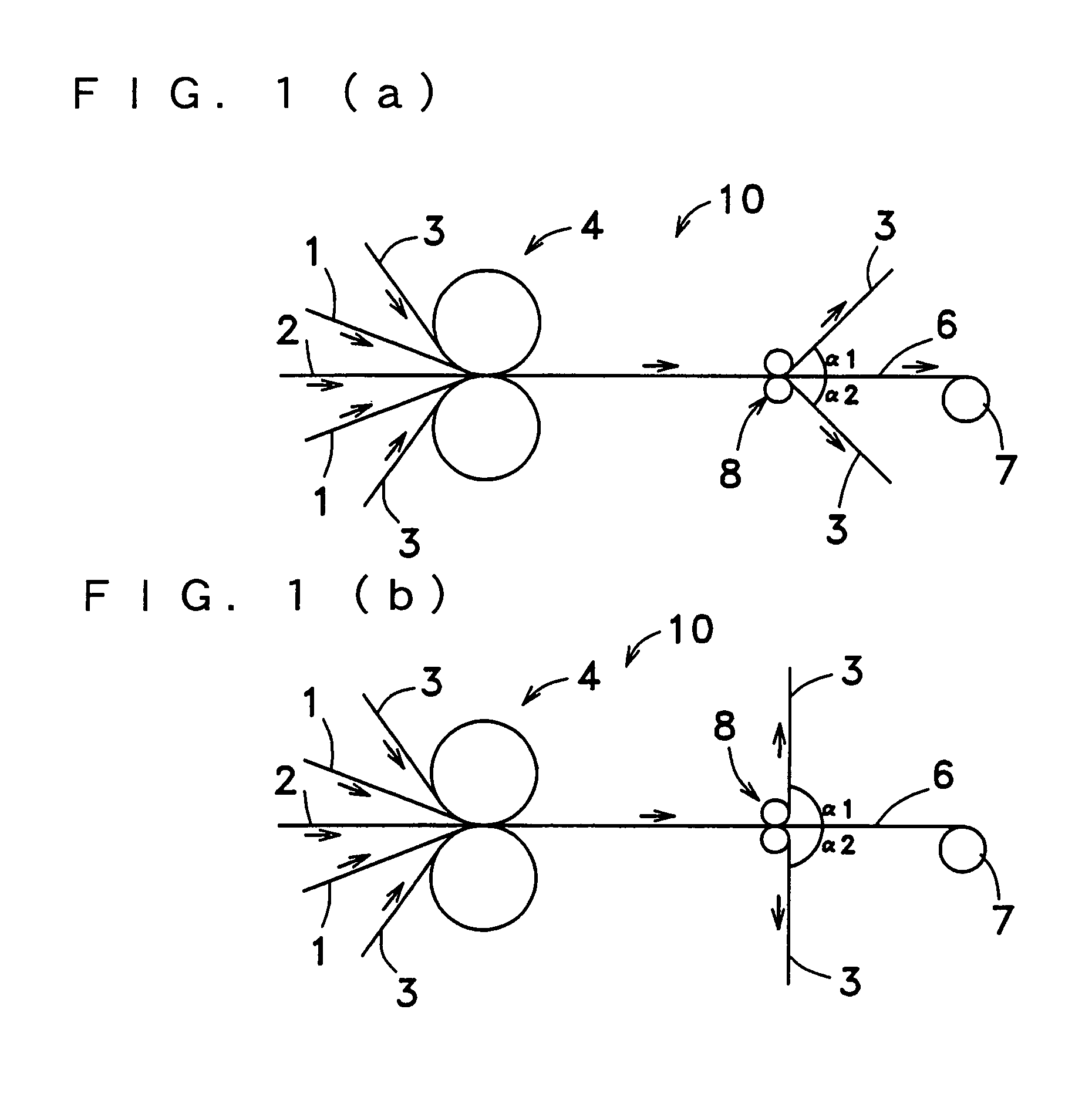
[0110]A laminating material was prepared by superimposing electrolytic copper foils having a thickness of 18 μm on both sides of a thermoplastic polyimide film having a thickness of 25 μm whose Tg is 190° C. (PIXEO TP-T produced by KANEKA CORPORATION). In addition, 125 μm-polyimide films (Apical 125AH produced by KANEKA CORPORATION) were superimposed on both sides of the laminating material as protective films. The laminating material was thermally pressured (temperature: 260° C., processing rate: 0.5 m / min, linear pressure: 980 N / cm) by a thermal-press forming device 10 shown in FIG. 3 (b). And then the protective films were peeled off after cooling the laminating material bonded by thermal pressure and the protective films in closely contact with the laminating material to room temperature to prepare a flexible laminate.

[0111]As a result, a flexible laminate free from visual defects such as wrinkles was obtained.

example 2

[0112]A flexible laminate was prepared in the same manner as in Example 1 except that rolled copper foils having a thickness of 18 μm which had more possibility of wrinkles were used instead of the electrolytic copper foils used in Example 1.

[0113]As a result, a flexible laminate free from visual defects such as wrinkles was obtained.

example 3

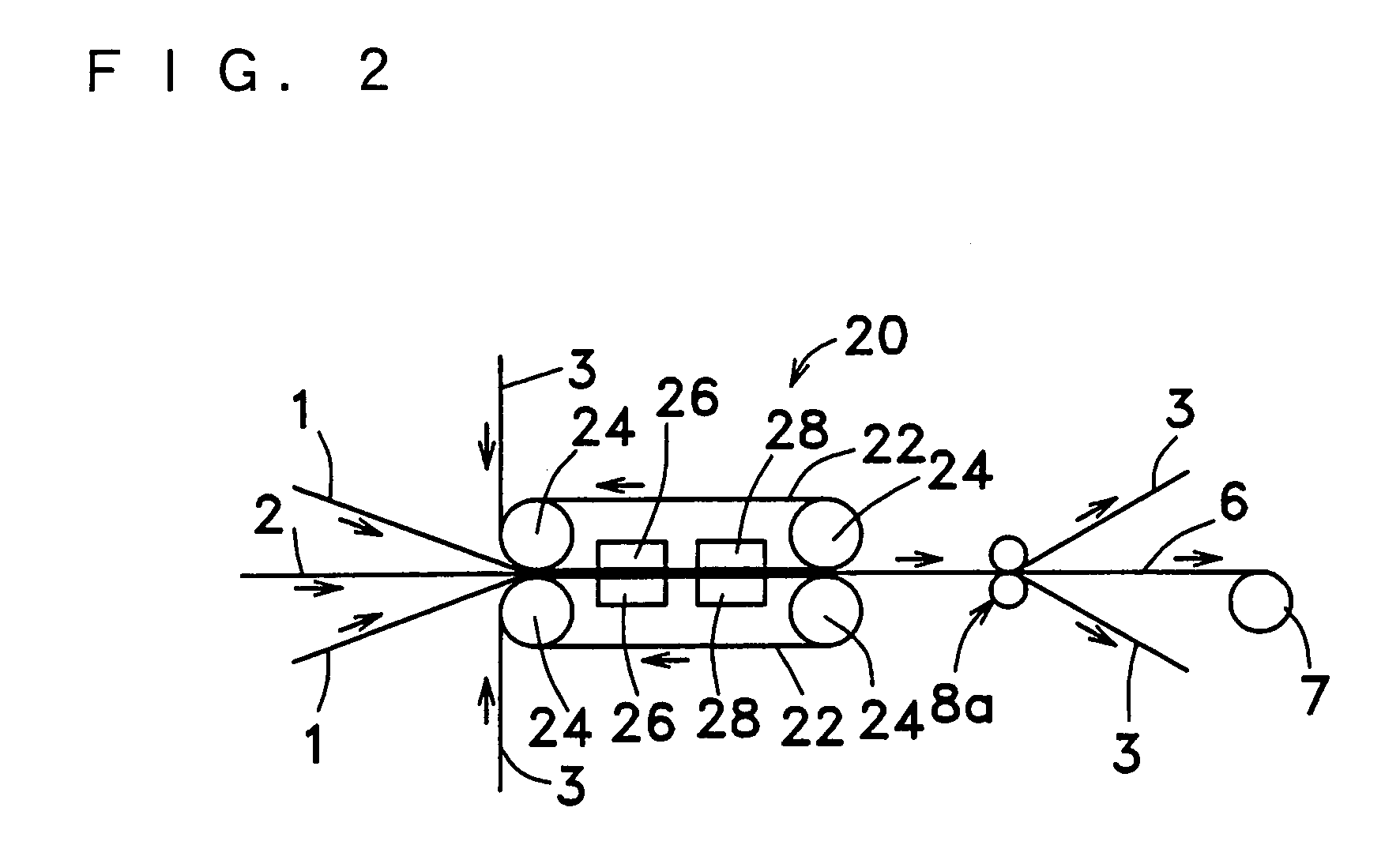
[0114]A flexible laminate was prepared in the same manner as in Example 1 except that a double-belt press (temperature: 300° C., processing rate: 0.5 m / min, linear pressure: 980 N / cm) was used instead of the thermal-press forming device used in Example 1.

[0115]As a result, a flexible laminate free from visual defects such as wrinkles was obtained.


PUM

PropertyMeasurementUnit
Temperatureaaaaaaaaaa
Percent by massaaaaaaaaaa
Temperatureaaaaaaaaaa

Abstract

The present invention provides a method for producing a laminate suitable for a flexible circuit board which is free from visual defects such as wrinkles and curls that appear when a plurality of laminating materials containing a thermally fusible laminating material are formed by thermally laminating these materials each other using a thermal-press forming device, which comprises the steps of: arranging a heat resistant protective material between a pressing surface and the laminating materials, laminating the materials by thermal pressure at not lower than 200° C., wherein the bonded laminating materials are in contact with the protective material, cooling the bonded laminating materials, and peeling off the protective material from the bonded laminating materials, whereby the laminate with less nonuniformity in pressurization, a uniform surface, and a good inter-layer adhesion, and the method and device for producing the laminate can be provided, more particularly, the thermal pressure and forming is performed by a thermal-press forming device having at least a pair of metal rolls.

Description

RELATED APPLICATIONS[0001]This application is a nationalization of PCT application PCT / JP00 / 07656 filed Oct. 30, 2000. This application claims priority from the PCT application and Japan Application Ser. No. 11 / 310,720 filed Nov. 1, 1999; Japan Application Serial No. 2000-126942 filed Apr. 27, 2000; Japan Application Serial No. 2000-126943 filed Apr. 27, 2000; Japan Application Serial No. 2000-244905 filed Aug. 11, 2000; Japan Application Serial No. 2000-248796 filed Aug. 18, 2000; Japan Application Serial No. 2000-248795 filed Aug. 18, 2000; and Japan Application Serial No. 2000-287552 filed Sep. 21, 2000.[0002]The present invention relates to a method and a device for producing a laminate using a thermal-press forming device. More particularly, the invention relates to a method and a device for producing a flexible laminate used for electronic and electric equipment.BACKGROUND ART[0003]Laminates used for printed circuit boards for electronic and electric equipment include laminate...

Claims


Application Information

Patent Timeline
IPC IPC(8): B32B37/04B32B37/06B32B37/08B32B37/12B32B37/20B32B38/10H05K3/02
CPCB32B37/0015B32B37/26H05K3/022B32B2309/14B32B2309/02
Inventor HASE, NAOKIKATAOKA, KOSUKEFURUTANI, HIROYUKIFUSHIKI, YASUO
Owner KANEKA CORP
Why Eureka
Try Eureka