Processing apparatus and method for fluid, and deaerator therewith

a technology of processing apparatus and fluid, which is applied in the direction of gas current separation, way, centrifugal wheel fertiliser, etc., can solve the problems of only being able to adjust the apparatus, reducing the dispersible range of viscosity of the fluid to be processed, and entanglement of the process process, etc., to achieve simple structure and high productivity rate

Inactive Publication Date: 2006-11-07
M TECH CO LTD
View PDF29 Cites 13 Cited by
  • Summary
  • Abstract
  • Description
  • Claims
  • Application Information

AI Technical Summary

Benefits of technology

[0118]In particular, the deaerator with atomizing apparatus in accordance with the nineteenth aspect of the present invention which employs as a atomizing apparatus the processing systems for fluid in accordance with any one of the fourteenth, fifteenth, and eighteenth aspects of the present invention may provide, for purpose of solution of said problems, a deaerator, of a simple structure and high productivity rate, which may perform accurate atomizing apparatus based on a unique idea that the shaft sealing mechanism for mechanical seal is used as means for atomization, set the interval between at least two processing faces rotatable relatively to each other to a predetermined micro-scale, supply a stronger shear force to fluid to be processed, and process the fluid in a broad range of viscosity as a deaering apparatus.
[0119]By adjusting the interval between the processing faces 1, 2 to a micro-scale one, the nineteenth to twenty-second aspects of the present invention may supply fluid to be processed with a shear force of necessary magnitude, thereby resulting in achievement of super atomization, which was unavailable in the past. That is, when fluid to be processed travels between the processing faces 1, 2, a stronger shear force may be given to the fluid in a certain micro-scale interval therebetween and the fluid will be sprayed through the interval, thereby atomization of the order under 10 microns is available, and so is the extraction of fine bubbles at the corresponding level. Namely, the interval between the processing portions 10, 20 can be reduced to such a size as unavailable by means of the conventional methods, which may lead to formation of finer bubbles.
[0120]In the nineteenth aspect of the present invention, a pressure control mechanism of applying pressure to fluid to be processed can be employed with the deaerator with atomizing apparatus of the first aspect of the present invention. Since this arrangement is capable of adjusting the interval between the first and second processing faces 1, 2, thickness of said fluid film will follow. Accordingly, desired atomization can be selected by said control, deaerating ability can be increased according to the properties of fluid to be processed in viscosity, and bubbles to be removed may be treated in terms of the size (fineness) carefully.

Problems solved by technology

As a first disadvantage consisting in this system, during process, friction between media, between the media and the agitating blades of the apparatus, between the media and the inner side of a container may bring about some chips ground from said matters so that said chips will be mixed into said fluid as impurity.
As a result, frequent supplement of loss due to friction with fresh media and exchange of parts are needed, thus entailing extra troubles and cost accordingly.
A second disadvantage is that application of a stronger shear force or demand of smaller particle diameter requires the use of media of smaller diameter than those in the past, for example, use is often made of fine media in the size of 0.05 or 0.1 millimeter in diameter, and there is a tendency to seek for media of relatively small diameter.
However, the smaller the diameter of media, the smaller the mass of each medium, which may cause decrease of the dispersible range of viscosity of the fluid to be processed with the consequence that only a substance of low viscosity is applicable.
In this case, the width of the interval can be determined mechanically by means of an adjusting handle, but the apparatus used is only capable of adjusting on the level of substantially more than several dozen microns (no adjustment was possible as to the level of less than 10 microns).
Further reduction of the width may incur the risk of a serious accident on account of the contacts of the disks as occurred by thermal expansion or run-out of the rotary shaft.
Also in this event, as in the case of the colloid mill, it is hard to adjust the width at the level of scores of micron.
And it is necessary to provide adequate crowns for further regulation of the pressure occurring between the rolls, which operation needs human skills and involves risks of accidents.
Moreover, the apparatus itself remains so opened that it is not useful for fluid containing rather evaporable solvent.
The former is employed as a pre-dispersing unit, but it is unavailable for precise dispersion.
The latter is known that when used as industrial equipment it, it is endowed with too many difficulties such as wear and tear of the orifice portion or stopping of capillary as well as seal wear of the booster pump.
Though having different particle sizes, these grinders are uneven on the surface, and when they handle hard a substance to be processed, there is possibility that raised portion will be scraped or worn out to cause inclusion of impurity.
According to the report, in pulverization of a substance to be processed that contains high fat, much moisture, high protein, sugar, and specific enzymes, such particular properties tend to change because of stickiness, scorching, or transformation into film due to frictional heating, so that said substance are not marketable as in the form of powder.
And if the peripheral velocity of the rotary whetstone has risen above a certain level, grinding ability thereof is rapidly increased, concurrently with the temperature rise due to frictional heat decreasing its degree, and when the peripheral velocity of 3,422 meters per minute has reached, problems in machine cost and mechanical security occur.Patent document 7: JP laid-open patent Application No.
After all, in the event of supplying a material to be processed under the atmospheric pressure, each of the aforementioned systems are incapable of narrowing the clearance between the two whetstones (grinding members) laid one upon another to less than 15 microns.
Namely, the foregoing clearance between the whetstones by means of the conventional mechanical means can not be suitable for micro-scale attrition or grinding.
Meanwhile, the use of said mills for attrition and grinding operations may cause inclusion of foreign substances (chips resulting from the contact between the mills or the mill and other matters), and a grinding apparatus which may safely rotate at high speed for high performance is not available.
The fine division of the textures of the punching plate and screen has a physical limit, so that they are not useful for removal of bubbles much finer than the textures of the punching plate and screen.
Said punching plate and screen cause nuisance of cleaning and removing of clogs thereof.

Method used


Image

  • Processing apparatus and method for fluid, and deaerator therewith
  • Processing apparatus and method for fluid, and deaerator therewith
  • Processing apparatus and method for fluid, and deaerator therewith

Examples


Embodiment Construction

[0121]The embodiments of the present invention will be described with reference to the drawings.

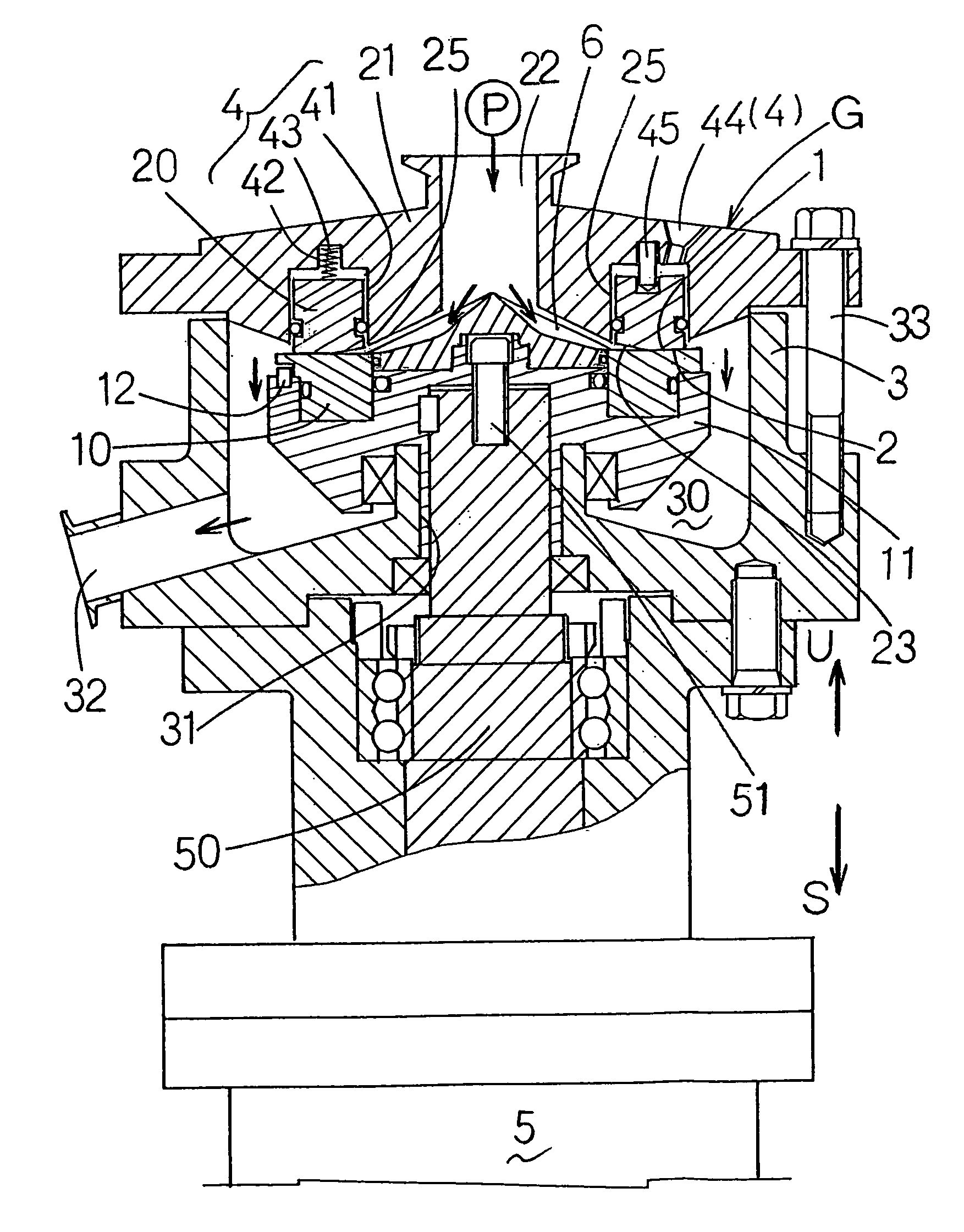
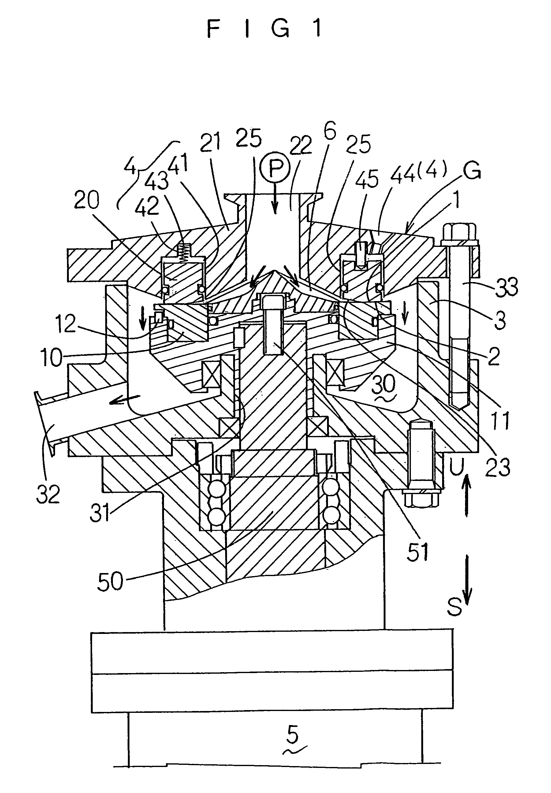
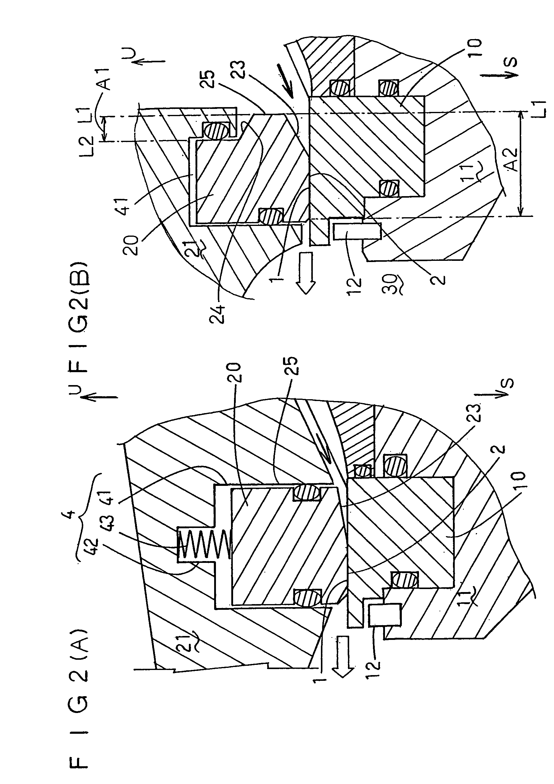
[0122]FIGS. 1 and 2(A) illustrate one embodiment of the present invention. FIG. 1 is a partially cutaway longitudinal sectional view of an atomizing apparatus G of a deaerator in accordance with the present invention. FIG. 2(A) is a longitudinal sectional view showing the main part of the deaerator as per FIG. 1.

[0123]For the convenience of explanation, an arrow U indicates the upward direction, and S the downward direction in the drawings.

[0124]First, the explanation will be made of the construction of the deaerator.

[0125]The deaerator comprises an atomizing apparatus G, and a known decompressing device (not shown in this embodiment) such as vacuum pump.

[0126]Said atomizing apparatus G is proper for atomizing operation of the order of microns to nanometers, specifically for the deaerating process for the removed (extracted) components from a single liquid, liquids, liquid and solid (powd...


PUM


Abstract

A processing apparatus for fluid with a simple structure, high productivity, ability of precise dispersion, emulsification and grinding, is provided.
The apparatus of the present invention comprises at least two processing faces of a first face and a second face, both of which are arranged in a tight-closed passage, and positioned opposite to each other to constitute part of said passage, and a contact pressure applying mechanism for putting both faces 1, 2 into closed contact with each other, wherein the rotation of the second processing face 2 in respect of the first processing face 1 may cause dispersion or emulsification of the fluid to be processed between both processing faces 1, 2. The first and second processing faces 1, 2 are placed in closed contact with or adjacent to each other by means of said contact pressure applying mechanism, and the fluid to be processed is actuated by said rotation to pass between the first and second processing faces 1, 2, as it is forming fluid films between said processing faces 1, 2, so that said fluid will be emulsified or dispersed to a desired extent.

Description

[0001]This nonprovisional application claims priority under 35 U.S.C. § 119 (a) on Patent Application No(s). 2002-207533, 2002-321018, and 2002-340374 filed in JAPAN on Jul. 16, 2002, Nov. 5, 2002, and Nov. 25, 2002, which is(are) herein incorporated by reference.FIELD OF THE INVENTION[0002]The present invention relates to a processing apparatus and method for fluid, and a deaerator with the apparatus.BACKGROUND OF THE INVENTION[0003]To begin with, description is made of the conventional art for the processed of dispersion and emulsification.[0004]There have been widely used dispersing systems generally called “media mill” in the producing systems for coating medium, inks, magnetic materials, ceramics, cells, adhesives, electronic materials, liquid crystal color filters, medicines, cosmetics, perfumes, foods, etc. This specific dispersing system is intended to obtain desired dispersion of fluid being processed by agitating said fluid being processed in the dispersion chamber filled ...

Claims


Application Information

Patent Timeline
Patent Type & Authority Patents(United States)
IPC IPC(8): B05B1/26B05B1/14B05B1/34B01F7/00B01F7/16
CPCB01F7/00758B01F7/00791B01F7/1625B01F2215/0409B01F2215/0431B01F27/271B01F27/2714B01F27/81
Inventor ENOMURA, MASAKAZU
Owner M TECH CO LTD
Why Eureka
Try Eureka